
Before getting into the formulas and calculations for designing a toroidal transformer, it is better to glide over the physics concepts that allow us to design and build such electric machines.
The physics principle according to which a transformer works is called Faraday’s Law.

This principle has to do with a correlation between the current flowing thought the wire of a solenoid and the magnetic field generated inside of it.

And it works in both directions!
If we apply a variable voltage to the leads of a solenoid, a variable current will be generated, and such variable current will generate a variable magnetic field inside the solenoid.
Also, if we take another solenoid and we submerge it inside the variable magnetic field of the first solenoid, a variable voltage will be generated at the leads of such solenoid, and if we apply a load to them, a variable current will flow.
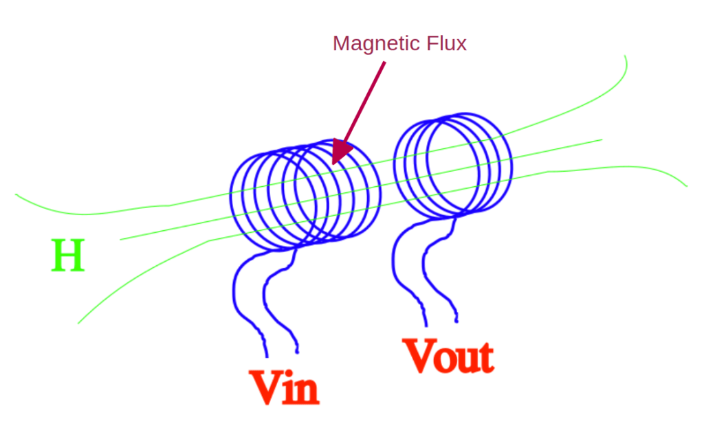
The most important part correlates the intensity of the magnetic field with the sectional area of the solenoid.
The magnetic field through a sectional area is called magnetic flux, and the flux density and intensity correlates directly with the amount of current that the created voltage can sustain.
To understand the concept of flux, think of a pipe with a specified sectional area where water flows inside. The larger the area, the larger the flux of water going through.
If we insert a ferromagnetic material inside the solenoid, the intensity of the magnetic field will be hundred of times stronger.
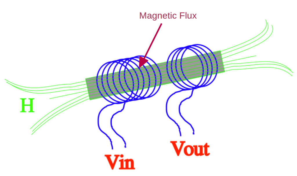
We call the ferromagnetic material inside the solenoid “core”. We call the solenoid used to generate the magnetic field “primary coil”. And we call the second solenoid “secondary coil”.
This is the working principle of the transformers.
And we can do even more. We can force the flow of the magnetic flux to turn around on itself, so we don’t waste any of it, thus reinforcing even more the transfer of energy from one solenoid to the other.

Here is how it works:
1) We apply a voltage to the solenoid on the left, which ends up generating a current in the wire.
2) The current generates a magnetic field through the whole magnetic core, imprisoned by it, so we don’t loose any part of it. And that creates a magnetic flux that moves along the path identified by the core.
3) The variable flux induces a voltage into the solenoid on the right. If we connect a load, such a resistor, to the leads of this solenoid, we obtain a current, even though the two solenoids are not electrically connected to each other.
Talking about transformers, the solenoid on the left is called “primary” , which is the coil where we inject the electric current. The solenoid on the right is called “secondary”, which is the coil where we extract the induced current.
The number of turns in the first solenoid and the number of turns in the second solenoid are also correlated.
The ratio between the number of turns in the primary and the number of turns in the secondary is directly proportional to the ratio of the voltage applied to the primary and the voltage induced at the secondary:
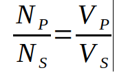
Therefore, we can calculate the voltage at the secondary if we know the voltage at the primary and the number of turns at both the primary and secondary coils:
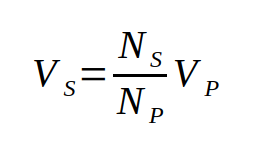
And this formula is at the base of any transformer calculation.
This other formula, instead, correlates the voltage with the magnetic flux and the number of turns:
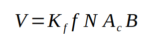
where:
Kf is the waveform coefficient, which we’ll talk about later
f is the frequency of the applied variable voltage
N is the number of turns of the solenoid, or coil
Ac is the sectional area of the magnetic core
B is the magnetic flux density
And such formula is, in fact, the result of Faraday’s Law applied to our case.
Materials
Now that we know that a transformer is made of two windings and one magnetic core in the shape of a closed loop, let’s see what kind of ferromagnetic material we can actually use to make the core.
Well, the thing is that the materials we can use for the cores physically depend on some electromagnetic parameters that we need to take into account when designing a transformer.
The parameters are:
1) the range of frequencies of the involved voltages and currents
2) The intensity of the currents and, therefore, the magnetic flux density
3) The max power at which the transformer is supposed to operate.
For that, we distinguish two main categories of materials that we can use to make a core:
1) ferrite cores
2) iron-silicon cores
Ferrite cores are used for high frequency applications, from audio frequencies up to radio frequencies.
Iron-silicon cores are used for power applications, with frequencies around 50-60 Hz.
And that depends on the capability of these materials to be able to handle the appropriate amount of magnetic flux without saturating, and the capability to conduct the right amount of flux without dissipating too much energy, property that is affected by their magnetic permeability mu.
Regardless of the application, the involved power, and the frequencies, all transformer calculations are basically regulated by the same formulas.
We will now go through all the basic calculations for the use case of a power transformer. But keep in mind that the same formulas and the same procedure can also be used for audio transformers and for RF transformers.
Specifications
Before we start the procedure, we need to define the specifications for the transformer we want to design. You’ll find most of them obvious, give what we have said already.
#1 is the input voltage, which we will represent with Vi
#2 is the output voltage, which we will represent with Vout
#3 is the output current, which we will represent with Iout
#4 is the frequency, which we will represent with the letter f
#5 is the application for this transformer, either power, or audio, or RF
#6 is the number of phases, which we’ll keep to 1 for this tutorial. Multiple phase transformers need a discussion on their own, and the most of us, interested only in electronics, won’t even care about them.
Procedure
Step 1:
calculate the power that will be handled by the transformer. This is very important for two reasons:
1) we need to size the wires section so that they will be able to handle the needed current.
2) we need to figure out the sectional area of the transformer core, which depends on the power that needs to be moved.
The first reason is obvious, because although the specifications give us the amount of current at the secondary, we still need to calculate the amount of current at the primary, and that needs to be done through the power.
The second reason is tied to the magnetic flux intensity in the core. The flux intensity depends on the sectional area, and the amount of power that can be transferred from the primary coil to the secondary coil is proportional to the amount of flux. The more the power, the more the flux. The more the flux, the larger the sectional area, according to Faraday’s law.
To calculate the involved power, we just need to multiply the voltage output by the current output:

which is expressed in VA, since we are dealing with alternate current.
Step 2:
adjustment of the power because of the transformer efficiency. The problem is that not all the power at the primary is going to be transferred to the secondary, and that’s because the core itself will dissipate some of the power, mostly because of the eddy currents that the variable magnetic field will try to induce in the core. The core material is designed in such a way to present a reasonably amount of magnetic permeability while, at the same time, a high resistance. And the high resistance reduces the eddy currents. Still, there will be some loss of power, and the core will warm up because of that.
Here is the formula that adjusts the power for the efficiency:

where VA is the actual power we need, Pout is the power calculated above, and eta is the efficiency, which is a pure number between 0 and 1.
In general, we can say that for a well designed transformer with toroidal core, it is safe to assume an efficiency around 90%, or eta = 0.9.
Step 3:
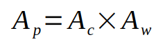
calculation of the core-area product. But what is this entity?
Well, this has something to do with the geometry of the core. Basically, it is the product between the sectional area of the core, Ac, and the area of the empty space surrounded by the core, which we call Aw, or window area. Here is the formula:
This entity correlates directly with the power VA that we calculated in the previous step. The correlation is through the Faraday’s law, adjusted to consider the mechanical measurements, the power of the transformer, and the maximum amount of flux that the core can handle without having its magnetic capabilities altered forever.
You can compare the max flux that a core can handle with the max amount of current that can flow through a wire. The max current depends on the sectional area of the wire and the material, whether it is copper or aluminum, or a different compound.
For the magnetic core, the max flux depends on the sectional area of the core and the material of which it is made. The window area comes into play when you consider the length of the path the flux has to go through, like in the case of the length of the wire a current has to go through. It also comes into place when considering the space the wire will occupy when winded around the core.
These entities are correlated through the following equation:
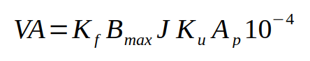
where:
VA is the adjusted power we calculated in step 2
Kf is the waveform coefficient, that depends on the shape of the voltage applied at the primary
Bmax is the mas flux density expressed in Tesla
J is the current density through the secondary
Ku is the winding utilization factor
The waveform coefficient comes out from the resolution of the integral in the Faraday’s law equation.
It is substantially the ratio between the rms value of the voltage divided by the average of the half wave of the voltage, multiplied by 4:

For example, for a sine wave, such value is about 4.44, while for a symmetrical square wave, since the rms and average values are the same, Kf is 4.
The current density J is the ratio between the current in the wire and the sectional area of the wire. It is expressed in A/mm2.
Ku, the winding utilization, is directly correlated with the space occupied by the wire when winded around the core, and therefore depends on its geometry. An acceptable value for a toroidal core is around 0.4.
Given all of that, we can now calculate the core area product rearranging the previous formula in this way:

The factor 10 to the power of 4 converts the result in centimeters to the power of 4, which is how this entity is expressed in the data sheets of the magnetic cores.
Step 4:
select the toroidal core we would like to use.
In this step we will need to consult the manufacturers data sheets for toroidal cores. They list various core sizes with their corresponding Ap value. If the data sheet does not report that value, use the window area Aw and the cross-sectional area Ac and calculate the Ap value as:

The data sheets also provide a value for Bmax. At this point reapply the equation for the determination of the Ap value with the new value of Bmax and, if that is smaller then the one we are using, go back to that step and recalculate the needed Ap using the given Bmax value. Then search for a better core. This step may take a while, as you’ll have to try multiple times until you find the core you need.
Step 5:
calculate number of turns per volt, or TPV.
The number of turns per volt is calculated using the following formula:

where:
Ac is measured in square centimeters
Bmax is measured in Tesla
f is measured in Hz
Kf = 4.44 for a sine wave
If the datasheet you are using provides Bmax expressed in Gauss, you’ll have to convert it into Tesla knowing that
1T = 10,000G.
Step 6:
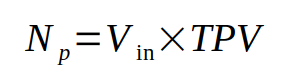
calculate number of primary turns Np.
Now that we have the number of turns for one volt, we can calculate the total number of turns in the primary by multiplying TPV by Vin:
Step 7:
calculate number of secondary turns Ns.
This calculation can be achieved in two different way. Choose the one that you like the most.
First option:
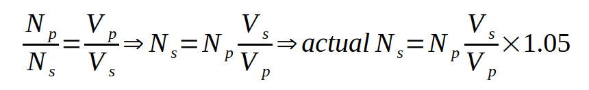
apply the same equation used to calculate the primary turns, but add 5% to adjust for losses during the transformation process:

Second option:
Use the known ratio of voltages to calculate the ratio of turns and add the same 5% correction:
Step 8:
calculate primary current Ip
The current at the primary needs to provide the power needed at the secondary:

Step 9:
select wire gauges of primary and secondary coils.
Based on the max amount of current flowing in the primary, select the most appropriate wire gauge to prevent coil overheating. Then do the same for the secondary coil.
We will call the sectional area of the primary wire

And we will call the sectional area of the secondary wire
Step 10:
estimate winding space.
This is a necessary step to make sure that we can fit both coils on the core we have chosen. In particular, we need to make sure that there is enough space in the toroidal window to fit all the turns and to leave some space in the center.
The total wire area for the primary will be equal to
The total wire area for the secondary will be equal to

The sum of these quantities + insulation area should not exceed about 40% of the window area Aw.
If that cannot be done, we will need to go back to step 4 and select a larger toroidal core. Then redo all the calculations starting from there.
And there you have it. The complete procedure to calculate a toroidal transformer, which you can also watch on this YouTube video:
You can use this procedure to design your own transformers, either for power supplies, or for small circuits that require a similar component to perform some kind of task. For example, an audio transformer to adapt the impedance between two elements in the audio chain, or a small transformer to create your own boost converter, and so on.
Just make sure, once you have done all your calculations, to go through them more than once and make sure everything is right. Especially with power transformers, a wrong calculation can cause a lot of damage or even cause harm to yourself and/or others.
It is your responsibility to make the proper calculations to avoid damage to objects and people.

