
This is the first of a new series of tutorials, with hands on experiments, to learn the basics of digital electronics. We will go together from the very basics information and we will move on illustrating first the building blocks of the digital circuits, and then continue the discussion introducing circuits more complex, like flip-flops, couters, multiplexers, and much more.
In each episode of the series we will add a little theory to the pile and will showcase simple digital circuits that you can build for a hands on learning experience.
In this blog, as a start, we will go through some important definitions and then I will provide you all you need to build a device that we will use a lot in the future episodes of this series: the logic probe.
This series of tutorials will also be backed up by a corresponding video series available on YouTube. The following page provides the links to the YouTube Videos, as well as the link for the whole series, and the link to all the files involved in the tutorials, with schematics and anything else that might be needed:
https://eleneasy.com/digital-electronics-fundamentals-articles-and-video-archives/
What is Digital Electronics
Digital Electronics is that branch of Electronics that involves the use of circuits that are capable of dealing with only two voltages, as opposed to Analog Electronics that works on circuits that handle voltages in an infinite range.
An example of analog electronics is a classic FM radio, which works with radio waves and produces sounds made of a continuous signal that can assume any value within the limits of the power supply of the circuit.
An example of digital electronics is the CPU of a computer, that deals with signals that can assume only two values, usually named Low State and Hgh State, or Low and High for short.
Circuits in the analog world are made of resistors, capacitors, inductors, transistors, and so forth.
Circuits in the digital world are made of logic gates, also know as logic ports, which are basically made with transistors working in the saturation region, so that they can be only off or on, therefore delivering only two possible signals: low and high.
Besides the possibility of actually making logic ports with transistors, we normally use pre-made ports packed in integrated circuits.
And, finally, while we sometimes need to use complex mathematics to deal with analog circuits, in the digital world we use only Boolean operators, which behave very similarly to the arithmetic operators like plus and minus. This actually helps a lot, because it is much more simple to deal with digital circuits than it is with analog circuits. Well, of course this is more of a subjective statement. Somebody might disagree on that.
Families
For the most part, digital circuits are available in the form of integrated circuits.
There is in fact a great compatibility on this kind of components, although made by different manufacturers. The thing is that digital circuit and signals are standardized, so it is easy to mix and match components from different vendors to build a specific circuit.
There is one thing, though, that we need to be careful about.
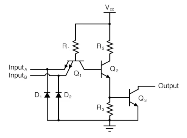
We said that logic ports are made of transistors. But there are different type of transistors. In particular, we use the bipolar transistors (BJT) and the field effect transistors (MOSFET).
With the bipolar transistors we can build logic circuits usually named TTL, or Transistor-Transistor Logic. These circuits are essentially made of transistors and resistors.
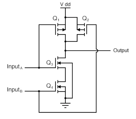
With field effect transistors, we can use together n-channel and P-channel MOSFETs to create simple logic gates.
Because we mix together p- and n-channel MOSFETs, the technology used by these transistors is named C-MOS, or complementary MOS. For each port we use one n-MOS transistor and one p-MOS transistor. One is the complement of the other. No resistors involved.
Digital circuits that use these components are said to be part of two different families: the TTL family and the CMOS family.
Why there are two of them?
Well, the first digital circuits were RTL and DTL, now obsolete, followed by TTL. They used a lot of space on the chip dies because they had to implement also the resistors to correctly polarize the transistors in the saturation zone.
Once the MOS technology became easier to use, the CMOS logic ports were created. In these, the two transistors are usually connected one against the other, so that when one is on the other one is off. This eliminates the need of resistors, since the off transistors, when off, behave like infinite resistances. It also reduces drastically the power needed to make the circuits work. A CMOS circuit can easily consume between 1,000 and 1,000,000 times less power than the corresponding TTL circuit.
In addition, CMOS circuits use less space on the die, allowing putting more components than TTL circuits in the same space, as you can see from these pictures.
There is a catch, though. CMOS devices are more difficult to handle because they are very sensitive to electrostatic discharges, and so they can break just by holding them in your hands.
In the simpler integrated circuits, there are protections in place on the die itself to limit the problem, but bigger devices, like CPUs, are very sensitive to electrostatic discharges, and so they need to be handled with extreme precaution.
In this series we will examine both TTL and CMOS technologies.
The TTL family is greatly used when there is a special need for speed, since the CMOS equivalents are slower, due to the intrinsic capacitance at the gate of the MOS transistors.
CMOS, however, use less space, and so their technology is preferred when building very complex devices, like a CPU.
And there is also a trend of building CMOS transistors smaller and smaller on the die. Smaller transistors have a smaller gate and, therefore a smaller capacitance, which leads to greater speed.
One last thing that differentiate the two families is the supply voltage.
The TTL family is usually limited to a supply voltage of +5V.
The CMOS family can be powered on a vast range of voltages, typically between 1.5V and 18V.
Logic States
Let’s now go back for a moment to the logic states.
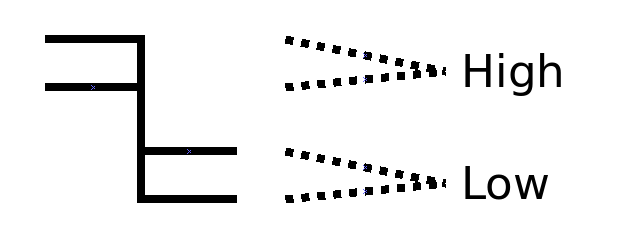
We have already said that all digital devices work on two states only, the high state and the low state, and they are associated with the supply voltage and the ground reference respectively. Any other value of voltage at the input or output of the logic devices is not supported. Or is it?

Well, sometimes, because the way a circuit is built, it is not possible to achieve exactly those voltage levels. What do we do then?
Put it simply, we define an acceptable range, and we say that all digital devices have to accept anything in that range as a high level. And we do similarly for the low level.
Now, thanks to this requirement, all the vendors that build digital devices, and follow such requirement, can be sure that their components will be compatible with similar components from other vendors, and so will be all the customers that buy these components. Welcome to standardization!
And now that we have established that digital devices work within voltage ranges rather than exact voltages, we can define a better way than call those states high and low, so nobody will get confused, because they won’t need anymore to think in terms of ranges.
The adopted way to do so is to use the terms of the boolean algebra, which was invented by George Bool way before the digital circuits were invented. George Bool created such algebra as a way to easily solve complex logic problems. He realized that any logic statement can be described to be either true or false. Combining several statements becomes then a matter of operating with these two states of true and false and, therefore, the analysis of several concurrent statements can be done simply by operating appropriately on these two states.
And so, thanks to that visionary mathematician, today we tend to associate the state TRUE with the high state of the digital circuits, and we associate the state FALSE with the low state.
And then came the engineers, and they said: why in the world we need to use TRUE and FALSE as the values for making calculations? Why don’t we use just numbers? We can associate the state TRUE with the number 1 and the state FALSE with the number 0. And we already have binary arithmetic, so we can easily converge these two concepts.
And that’s why today we use the values of 1 and 0 when we work with digital electronics.
With ones and zeros, we can create a so-called abstraction layer when we do digital circuits design. We can ignore the fact that we are working with TTL circuits or with CMOS circuits, so we don’t have to worry about voltage values which, we know, are not the same with the two families of circuits.
Only when the design of the logic is done, and we need to implement it in circuits, then and only then we translate ones and zeros in voltages.
And because we have a standard to follow, everything will work just fine.

From the first two rows of this table we can see that for TTL circuits, which are powered with 5V, everything above 2.3V is a logic 1, and everything below 0.08V is a logic 0.
For the CMOS family, since these devices can be powered at different voltages, we have a 1 when the voltage exceeds 70% of the value of the supply voltage, and we have a 0 when the voltage is below 30% of the value of the supply voltage.
We won’t talk for now about other details on these families, but we will get back to that in the future.
Measuring The States
OK, now the problem is: how do we take measurements of digital signals?
Can we use a multimeter? Of course we can, but then we need to remember the specs to make sure that the voltages we read are within the required ranges to be a 1 or a 0. Possible, but not practical.
Can we use an oscilloscope? Same thing: we read voltages, and we need to convert them in our mind to figure out if they are ones or zeros.
And so… is there a practical way to make measurements of digital values?
But of course there is. There are at least two ways.
Way number 1.
We use a so-called logic analyzer. It is like an oscilloscope, but it is capable of making all the calculations to see if the voltages are in the correct ranges to be a 1 or a 0, and then they show directly a wave signal that represents only those values as Vcc or ground; no ranges whatsoever. These devices have also several channels, so you can usually watch 16 or more digital signals at once. That is very practical but… logical analyzers cost money. They cost at least like a good multitrack oscilloscope.
What if we don’t want to spend that amount of money to work on our small projects at home?
Well, in that case…
Way number 2.
We use a so-called logic probe. A logic probe is a small device, capable of testing just one single signal at a time, and tells us if that signal represents a one or a zero using just a pair of LEDs.
There are logic probes capable of doing that on TTL signals, and there are those that are capable of doing that on CMOS signals.
I’m going to show you now the schematic of one that can do both, one that is capable of measuring both TTL and CMOS signals. And you can build one with just a few bucks, it is a very cheap device. To see how to make one, please head to the corresponding video on YouTube, accessible through this page:
https://eleneasy.com/digital-electronics-fundamentals-articles-and-video-archives/
Only when you outgrow this device, because you start working on complicated circuits that require watching multiple signals at once, you will have to buy and use an actual logic analyzer. Until then, this little device will do its job very well for many years to come. Even if you, one day, decide to buy a logic analyzer, the logic probe will still be there for you to use when you don’t need the whole power of the mighty logic analyzer.
That said, let’s take a look at the schematic of such a useful device.
The Schematic
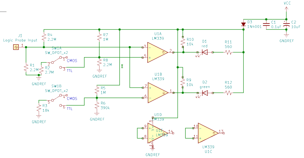
Our logic probe is built around a couple of voltage comparators, part of an integrated circuit that contains 4 of them. We are not going to use the two extra ones.
Why comparators? But, of course, to be able to measure voltage ranges, so the device will take care of making all the conversions between voltages and the logic levels.
The device will be powered by the same circuit under test, so it will be able to know what the value of the supply voltage is, and make its deductions in terms of converting the voltages in logic states.
The diode D3 is there to prevent the circuit from burning out in case we reverse the polarity when we connect the device to the circuit under test.
The tip of probe, on the left, sends the input signal we want to measure to the two comparators. The one on the top will measure the upper range, to see if the voltage is equivalent to a 1. We will therefore connect the probe to its inverting input, while on the non-inverting input we will put the minimum voltage of the range. Whenever the voltage at the inverting pin will exceed the voltage at the non inverting pin, the output of the comparator will go low, turning on the LED D1, which we will choose of red color.
Similarly, to detect a zero, we apply the input voltage to the non-inverting input of the second comparator. The inverting input, instead, will be connected to the maximum possible voltage of the range that represents the zero. This way, whenever the input signal is lower than the signal on the inverting input, the input of the comparator will go low and will turn on LED D2, which I have chosen to be green.
We also have a switch that allows us to change the reference voltages for the comparators, depending on the logic family we are working with: CMOS or TTL. For CMOS circuits, we set the switch to open, and the voltage dividers made of R7 and R8, and the one made with R5 and R6, will generate the 70% and the 30% of the supply voltage, which are the range boundaries of the digital signals.
For TTL circuits, we will close the switch, which will put a couple more resistors in parallel to those that make the voltage dividers. These new resistors, when the probe is powered with 5V from the circuit under test, will make sure that the reference voltages will be the ones for the TTL circuits: 2.3V for the 1 and 0.08V for the 0.
To use the device, we set the switch on the appropriate position, then we power the probe connecting it to the power supply of the device under test, then we use the probe terminal to read the signals. Depending on the LED that will turn on, we will know if the signal was a 1 or a zero. And if no LED turns on, it means that there is no signal, or that the signal is not in the correct range to be a valid 1 or 0.
We are going to use this simple device in many episodes of this tutorial, in the hands on sections. It will turn out to be very useful to understand how the proposed circuits work, and will help us acquire a practical view on the insights of digital electronics.
See you soon in this space and…
Happy experiments!


From Joe Labut YES. This is going to be helpful, back to the basics.
LikeLike
That’s the idea!
LikeLike
Back to basics!
LikeLiked by 1 person