Last month, a reader of this blog asked me a question about the possibility of measuring the resistivity of a powder mixture he created. We initiated a private conversation on the topic, and we ended up agreeing to work together to make such a measurement. He would provide me with the powder he created, and I would make the measurement for him, since he doesn’t have the lab resources for such a task.
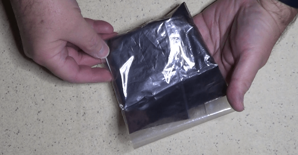
I received the material for running the test in just a week, although coming from overseas (Belfast, Ireland). It was packaged in a double layer plastic envelop, given that it is a very light powder and can go airborne very easily. To avoid spreading it across my whole lab, I handled it wearing a mask, so that my breath would not make it fly all over the places. The mask helped also in preventing me from breathing it.
Given the consistency of this powder, I had to think at a way to easily shape it in a form that would be kept intact while I was taking the measurements on it. So I had to create a container that would also provide some sort of electrodes to electrically connect the powder to my DMM (Digital Multi Meter).
But let’s proceed in order. And let’s begin with some general information about resistivity and methods to evaluate it.
Let’s start by providing a formal definition of the electrical resistivity. That is the property of any conductive material that defines its resistance to an electric current in terms of its shape and dimensions.
https://en.wikipedia.org/wiki/Electrical_resistivity_and_conductivity
If we take a material in the shape of a cylinder, for example, the resistivity is the ratio between the electric field applied at the two bases of the cylinder and the resulting current density.

If you think about it, the electric field applied to the cylinder can be translated in a voltage per unit of length, while the current density is nothing else than a current per unit of area.
If we consider the ratio between the applied voltage and the resulting current, we obtain a resistance. Such resistance is a function of the length of the conductor and the area of its sectional surface. The constant that correlates the resistance with the length and the area is what is called resistivity, usually indicated with the Greek letter rho.

Experimentally, we also notice that the resistivity depends also on the temperature of the material, on the impurities in the material, and on the mechanical stress to which the material is subject.
Therefore, when making a resistivity measurement, we also have to specify such conditions, in particular the temperature and the stress.
So, how do we make such a measurement?
Of all the methods that have been used to do such a thing, the two most relevant are the 4-point method, or Kelvin method, and the Wheatstone Bridge method.
https://en.wikipedia.org/wiki/Four-terminal_sensing
https://en.wikipedia.org/wiki/Wheatstone_bridge
The first is normally used to measure the resistivity of thin films or bulk materials.
The second is normally used to measure the resistivity of a material in the form of an electrical wire of known length and cross-sectional area.
Now, because the resistivity measurement can be done with a great precision with the 4-point method, given that I do have a lab instrument capable of automatically perform such measurement and calculate the result with a 4 and a half digit precision, I decided to use this method over the Wheatstone Bridge.
Note that I will actually measure the resistance obtained by dividing the voltage by the current involved in the measurement circuit.
Once the resistance of the sample is measured, I will be able to calculate the resistivity by inverting the formula normally used to calculate the resistance.

Since I have a powder to measure, I have to use a container to hold it, which would also allow me to easily add electrodes to connect the instrumentation.
The first choice for a container was one that resembles an actual commercial resistor: a cylinder.

I actually designed two of them, thinking of using both to average the measurements.
The design consisted of a simple pipe with caps that would fit the two ends to trap the powder inside. Holes on the caps would be used to pass through the conductors attached to metal plates on the inside of the caps, to establish the contact with the powder.
I inserted a screw on each hole from the inside, after fitting on each a couple of metallic washers with the function of conductive metal plate. On the outside, I added extra wiring connectors to make it easy to connect my digital multimeter.

After installing a cap on one end of the first cylinder, I started filling it with the mix of graphite and ash. That, actually, wasn’t an easy task, since the powder tended to remain attached all over the places, rather than going into the pipe.
But I did it, and finally closed the pipe with the second cap. While doing that, the pressure of the air between the cap and the pipe expelled some powder, so I decided to seal the cap with some tape, to stay on the safe side.
Unfortunately, that did not help, as enough dust came out of the pipe to make the powder inside loose enough to compromise the readings. But I discovered that only later.
I realized that the measurement did not work when I started tapping on the external surface of the pipe and the resistance reading started changing substantially. Only at that point I figured that while capping the pipe I lost enough powder to leave it very loose inside the pipe. The method I employed was not working!
The good thing about this first attempt is that I learned a couple of important things:
– first, I had to create a vessel that would not loose powder once I closed it
– second, I had to make a vessel in such a way that I could change the pressure of the powder inside to see how that would affect the value of resistivity.
So, I ended up using a totally different shape, the one you can see in this new design.
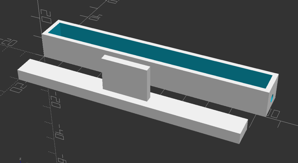
Besides the different shape of the cross-section, which was now squared, the major difference in this design is the position of the opening. Instead of having two openings at the two ends, I created a vessel with a single opening going through the whole length of the device. That way, a single cap could be used to close the hole and also act as a piston to compress the dust.
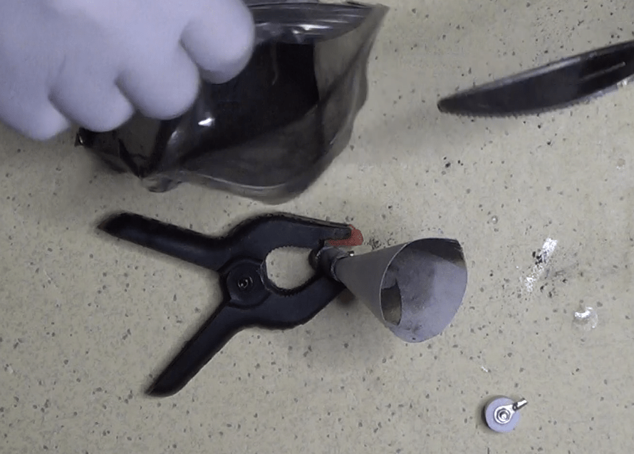
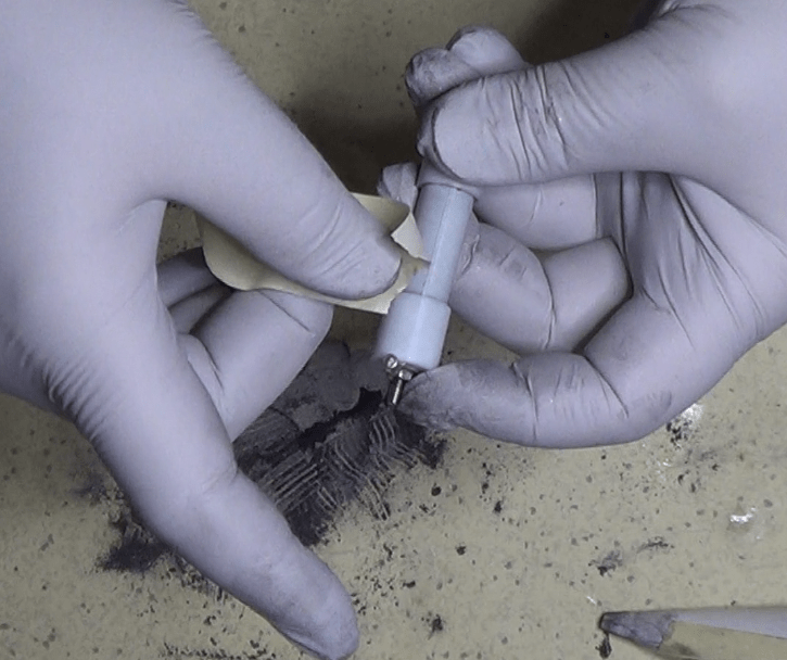
When mounting the probe terminals, this time I didn’t use washers like in the previous case. Instead, I used this coating that, once dried, leaves a layer of pure silver on the treated surface.

This has two advantages with respect of the previous solution:
– first, a thick layer can be lay down very easily and uniformly
– second, silver is the best conductor known on the face of the planet, so its interference with the precision of the measurement is really negligible.

I stopped filling the vessel once I reached a height of 5mm, then I cleaned up the top of it the best I could, and carefully covered everything with the lid.

Note that the lid is made of a very light piece of PLA, so its weight is negligible compared with the atmospheric pressure acting on it. And to prevent the lid from moving or to change the pressure inadvertently, I fixed it in place with some masking tape. The whole thing is done in such a way that there is no extra pressure applied to the dust. However, if i use my fingers to push on the lid itself, I can still manually apply some extra pressure to see how it affects the resistivity of the material.
It was time to make a new set of measurements, so I fired up my DMM, I set it up to do the 4-point resistance measurement, and connected the 4 probes to the external connectors of the vessel.
Then I took my first reading, which was of 20.9 ohms. I also shook a little bit the vessel to make sure the powder was packed but not under additional pressure, and the reading did not change. That was exactly what I wanted to see.

And with that reading I calculated the value of resistivity at the atmospheric pressure, which was 10.45 ohm mm, or 0.01045 ohm m. And of course I also noted the temperature of the room during the experiment, which was about 72F or 22 degrees Celsius. Temperature changes the value of the resistivity, so it is important to know the temperature reading during the experiment.
I then repeated the process applying pressure on the vessel lid and made a few readings at different pressure values, recording all the numbers I took.
I found that increasing the pressure would lower the resistivity, until I reached a pressure of 22.563 kPA on top of the atmospheric pressure. At that point, any increase in pressure did not produce a decrease in the resistivity.

Two words about the pressure measurements, which were an important part of the procedure.
I basically used this precision scale to measure the weight exercised by my fingers on the lid. Then, knowing the area of the lid exposed to the powder, I was able to calculate the actual pressure.

At that value of pressure, and higher, I measured a resistance of 9.20 ohm, and therefore a value of resistivity of 4.6 ohm mm, or 0.0046 ohm m.
With that value, and the previous measurements at different pressures, I was able to determine that the resistivity decreased almost linearly with the increase of the pressure, and came out with this graphic representation.

For further details, here is the video I posted on YouTube on the same topic.