
When we think of an electric circuit, the first thing that comes to mind is a bunch of electric and electronic components put together to make a device that provides a certain functionality.
This is totally right, of course, but it is not a precise definition of an electric circuit. In fact, circuits can be defined in different ways, depending on the particular aspect of them that we want to highlight.
If we want to define a circuit with respect to the wave length of the voltage and current that the circuit handles, we will distinguish between “lumped” and “distributed” circuits.
If instead we want to highlight the kind of electric or electronic components the circuit is made of, then we need to talk about linear and non-linear circuits.
And, finally, depending on the temporal stability of the components, we can talk about “time-invariant” and “time-variant” circuits.
And, of course, we can consider combinations of the properties and, therefore, combinations of different circuit types.
In this article, I will go through the above list of circuit types and provide a proper definition and description of each one of them. Combination of those types will lead to combined definitions and descriptions of the basic types. However, in this context, I will go through only the basic types of circuit, leaving to you the task to provide definitions and descriptions of the combinations.
Lumped and Distributed Circuits
Let’s go now into more details about these kind of circuits. What differentiates these circuits is the size of their components compared to the size of the wavelength of the electric current flowing through them. Hum, well, I guess we need to back up a little bit first. Let’s start with the types of current.
We have two kind of currents: the direct current, or DC, and the alternate current, or AC. DC current always flows in the same direction and never changes. AC current has usually the shape of a sine wave, or some other shape that periodically inverts the direction of the current. The number of times the current inverts its flow depends on the number of times the voltage flips its polarity. When the Voltage goes from positive to negative n number of times in a second, we say that its frequency is n and it is measured in Hertz.
Since the flow of the current in a conductor is not instantaneous, it makes sense to think that a change in the voltage at the ends of a conductor makes the current change progressively through the conductor. And if the voltage keeps changing back and forth, so does the current. At the end, both the instantaneous values of the current and the voltage across the length of the conductor follow in space the same shape of the voltage changes (in time) applied at the ends of the conductor. So, if the voltage changes in time like a sine wave at the ends of the conductor, it will follow a similar shape in space throughout the length of the conductor. The length of such a sine wave in space throughout the conductor is called wavelength of the voltage, or the current. Such length in space depends on the length in time of the corresponding voltage applied at the ends of the conductor.
We can calculate the wavelength using the following formula:

The Greek letter “lambda” represents the wavelength, the f represents the frequency of the voltage, which is how many times the voltage goes from positive to negative and back in one second. And, finally, the letter ‘c’ represents the speed of light. Yes, you got it right, it is the speed of light!
When the wavelength is much longer than the physical size of the components of the circuit, we say that it is a lumped circuit, because the components are just small lumps with respect to the wavelength itself. In such a case voltage and current are practically constant across the whole length of the component.

When the wavelength is comparable with the physical size of the components of the circuit, we say that it is a distributed circuit, because the components are so big compared with the size of the wavelength that the wave itself is distributed across them. In such a case voltage and current will be different in different sections of the component, at any instant in time.
Distributed circuits cannot be analyzed with normal algebra equations. For those, it is necessary to heavily use calculus. Example of such circuits are the microwave circuits, those used to deal with radars and satellite signals.
Linear and Non-Linear Circuits
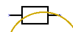
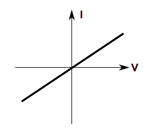
A component is defined as linear if it can be represented in a I-V (current-voltage) diagram with a straight line.
A component is defined as not linear if its representation on a I-V diagram is not a straight line.
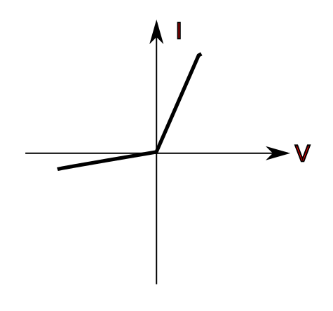
Simply put, a linear circuit is one made with only linear components, while a non-linear circuit is one that has at least one non-linear component.
Note the difference: for a circuit to be linear, ALL the components must be linear; for a circuit to be non-linear, it is enough that ONLY ONE component is non-linear. All the other components can be linear and still the whole circuit is non linear.
Time-Invariant and Time-Variant Circuits
Difference between time-invariant and time-variant circuits is also straightforward.
A time-invariant component is one for which the measurements that define it never change over time.
A time-variant component is one for which the measurements that define it can change over time.
As a result, a time-invariant circuit is one made only with time-invariant components. A time-variant circuit is one made with at least one time-variant component. This is a subtle definition, very similar in its form to the one for linear and non-linear circuits.
Circuits in Series and in Parallel
One last thing I would like to discuss about circuits in general is related on their topology or, in other words, on how the components in a circuit are connected to each other.
There are two main configurations of connected components:
- components in series
- components in parallel
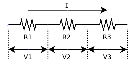
Components are said to be connected in series when they are traversed by the same current.
Components are said to be connected in parallel when the voltage on each one of them is the same.
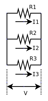
When we talk about connections in series and in parallel, of course, we refer to components directly attached to one another, at least on one terminal, or lead. Components that are far away in the circuit diagram, or that are not directly connected together cannot be defined as in series or in parallel.
So, now, can you tell me what kind of circuit is the one at the very beginning of this article? Put your answer in the comments and let’s see who gets it right.

