
Operational Amplifiers or, in short, op-amps, are encountered very often in analog circuits to make amplifiers, filters, comparators and oscillators. They are widely used for the simplicity that can be obtained in the design of circuits, but also for the advantages of improved stability, precision and linearity.
All these advantages come from the hidden complexity of their own design, that allows us to build the same complexity in our circuits while keeping them simple.
What is an Op-Amp?
An op-amp is an integrated circuit (IC) providing an amplifier with two inputs and one output. The output voltage is proportional to the difference of the voltages at the two inputs. The electrical symbol is depicted above. The two inputs are marked with a + and with a –. These are called the non-inverting input and the inverting input respectively.
These devices are usually powered with two separate voltages with respect to the ground. Powering them this way allows us to deal with analog signals without the need of using capacitors to decouple the signals from DC.
The op-amp gain, or the ratio between the output and the input voltages, is very high. Depending on the particular IC , it can easily range between values of 100,000 to several millions.
Based on that, for all practical purposes, we usually approximate our calculations by assuming that an op-amp has infinite gain.
Because of the infinite gain, and because the op-amp amplifies the difference between its two inputs, such difference has to be 0. Any difference greater than 0 would cause an infinite output voltage. Practically a saturation of the device.
Finally, both + and – inputs of the op-amp have a very high impedance, which we can again approximate with infinite. Therefore, we can safely say than when we connect a voltage source to any of the inputs there will be no current flow.
Here is a picture of the inside of a typical op-amp, in this case a LM741. You can see that it was no joke when I said that they hide a very complex circuitry on their inside.
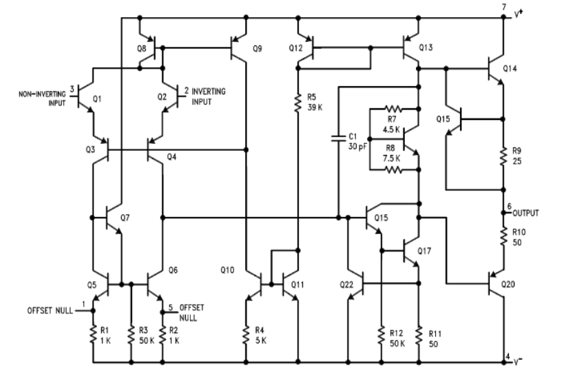
However, to use an op-amp we do not need to know how it is made inside. We only need to know how to approach the calculations at a black box level.
The easiest way to do so is to study some of their applications, which will help us understand how to deal with these versatile components.
The Inverting Amplifier
An inverting amplifier is one that takes the input signal, it amplifies it, and it presents it to the output with an upside down shape. We say that the output is shifted 1800.
Here is a representation of the signals in such circuit:

Note the input wave in yellow and the output wave in blue. You can see that the output exactly mirrors the input, but upside down.
And here is the schematic of the inverting amplifier:
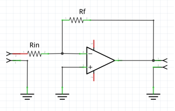
The non-inverting input is connected directly to ground. The inverting input is connected with a resistor Rf to the output, and a resistor Rin to the input voltage.
The Rf resistor provides a negative feedback to the amplifier. In fact, since the output voltage has opposite sign of the input voltage, the two signals cancel each other at the junction point between the two resistors Rf and Rin.
Let’s do some simple calculation now.
Since the two inputs need to be at the same voltage, and since the non-inverting input is connected to ground, the voltage at the inverting input must also be to a voltage equivalent to ground. We call this condition as virtual ground and we say that the inverting input is at virtual ground. Keep this in mind, because this is the main factor to determine how this circuit works.
Since the – input is at V=0, the current Iin inside resistor Rin will simply be:

and, similarly, the current If through resistor Rf will be:

Both Iin and If go toward the node at the – input. And since there is no current going out, it means that the two currents Iin and If must be equal in magnitude and opposite in sign, so

Substituting with the values of currents we calculated earlier, we obtain:

and rearranging:

So, the amplification of this circuit is simply obtained by the ratio between those two resistors and the output voltage will have an opposite sign than the input voltage. And that’s why this circuit is called an INVERTING amplifier.
The Non-Inverting Amplifier
This amplifier works similarly to the inverting one, but the main difference is that it does not shift the signal of 1800.
Here is a sample of the input and output signals in such an amplifier:

You can see how this time the output and input are in sync, there is no phase shift. In other words, the output is not upside down.
Here is the schematic of the non-inverting amplifier:
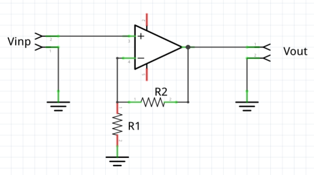
This time, the input voltage goes directly to the non-inverting input.
The inverting input is attached to the output through a resistor R2 and it is also attached to ground through resistor R1.
R2 and R1 create the negative feedback for the op-amp.
Because there is no current flowing in or out the inverting input, we can safely say that V-, the voltage applied to the inverting input, is given by the output voltage Vout going through the voltage divider made of R2 and R1. So:

We also know that the voltage at the two inputs must be the same, so V+ must be equal to V-, and also V+ is the same as Vin.
Therefore, we can write the following:

which can be rearranged this way:

So the amplification of this circuit, besides the sign, is just one point higher than the case of the inverting amplifier, but still depending only on the two resistors R1 and R2.
The Voltage Follower
The voltage follower is one of the two easiest circuits that can be created around an op-amp. In fact, there are no components directly associated with this functionality, just the op-amp.
Here is the schematic:

The output is directly connected to the inverting input, while the non-inverting input is used as the device input. Since the feedback loop applies the whole output to the inverting input, and since the two inputs have to be at the same voltage, This device produces at its output the exact same signal present at the non-inverting input.
Now you may ask: why do we care? We already had that signal, why don’t use that directly?
Well, the answer is: impedance!
When we put a voltage follower in between two other circuits, we do have what we call an impedance adaptation. We adapt the impedance of the circuit at the left of the voltage follower to the impedance of the circuit at the right.
As an example, let’s say that we have an oscillator, and we want to use its output to drive another circuit that is going to draw from the oscillator a certain amount of current. Unfortunately, if we draw current from it, the oscillator will stop oscillating.
The solution is to put the output of the oscillator as input to the voltage follower. Given the high impedance of the op-amp input, we will not draw any current from the oscillator, so it will work flawlessly.
But now we can use the output of the op-amp, which has the same signal as the oscillator, to draw the current we need, which is possible because of the very low impedance of the output of the op-amp.
Here is a picture representing the situation in the example:

The Voltage Comparator
And here is the other simple circuit that can be created with an op-amp:
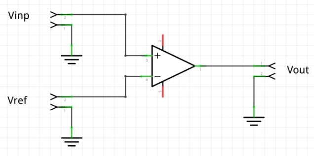
There it is. Nothing else. Not even the negative feedback connection!
Well, what is going on here? Simply put, with this circuit we want to actually exploit the extreme gain of the op-amp bringing it into saturation, that’s why there is no feedback.
We just put a reference voltage on the inverting input. Then we put a signal to the non-inverting input. What we want to achieve is to be able to say when the input signal on the non-inverting input is higher or lower than the reference voltage.
And in fact, when the input signal is greater than the reference voltage, the op-amp will saturate and will output the maximum possible voltage, which will be just a little less than the positive voltage provided by the power supply.
Vice versa, when the input signal is lower than the reference voltage, the op-amp will saturate again, but in the opposite direction: it will output the minimum possible voltage, which is very close to the negative voltage provided by the power supply.
We can consider, for example, the positive output as a logical 1 and the negative output as a logical 0. So we will have an output of 1 when the input signal exceeds the reference voltage, and we will have an output of 0 otherwise.
The Current Generator
Let’s now make an example of a current generator:

In this schematic there are only two resistors. RL is the load through which we want a constant current. R is used to complete the polarization for the negative feedback.
Let’s see how this works and how we can calculate the amount of current we need.
The voltage at the inverting input V- depends on the output voltage Vout reduced by the voltage divider made by resistors RL and R:

At the non-inverting input we have

which is a reference voltage.
The output current is given by:

since there is no current going through the wire toward the inverting input. And since V+ and V- must be identical, then we can write:

which we can adjust this way:

Now we can substitute Vout in the equation for the current, and we obtain:

So, basically, the current depends only on the values of the resistor R and the reference voltage. Even if the load RL changes, the current will not. So we have a constant current going through the load.
In addition, if we want to change the value of the current, we just need to change the reference voltage, without touching anything else, since the current is directly proportional to Vref.
The Voltage Adder
Another interesting circuit to analyze is the voltage adder. Algebraic operations are actually the reason why the op-amp has its name. It was originally designed to perform mathematical operations analogically. Of course that was before the advent of the digital circuits.
Let’s take a look at the circuit:

We have the op-amp with a negative feedback given by resistor Rf. The non-inverting input goes to ground and the inverting input is connected with a number of inputs via resistors that have all the same value, which we identify with R. At each input, we have a different voltage: Vin1, Vin2, and Vin3.
First thing to notice is that, since the non-inverting input is connected directly to ground, the inverting input itself is at the virtual ground. That said, we can calculate current If going through resistor Rf as:

Similarly, we can calculate the current across each resistor R as:

Since there is no current going toward the inverting input, it has to be:

And because of the previous equations on the current, we can now write:

and then:

which means that the output is proportional to the sum of the three voltages at the three inputs, but with a reversed polarity.
If we use a value of Rf equal to the value of the resistors R, the output voltage is exactly equal to the negative of the sum of the input voltages.
The Differential Input Amplifier
An important circuit built around the op-amp is the differential input amplifier. Here is its schematic:

First, we can see the feedback resistor R, connected between the output and the inverting input.
Then there are two input resistors and a fourth resistor between the non-inverting input and ground.
All the 4 resistors have the same value.
Once again, and this is very important for this circuit, remember that the values V+ and V– have to be the same, .
Based on that, here is the sequence of calculations that lead to the final result:
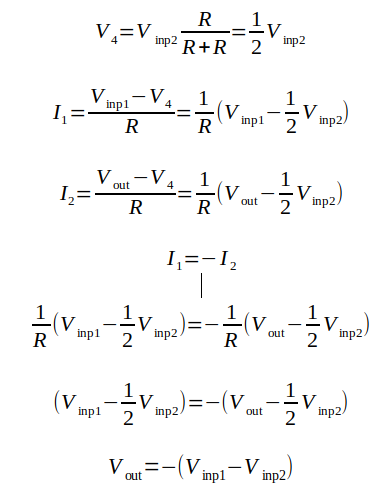
Let’s just take a look at the final result. That tells us that the output voltage is exactly equal to the difference of the voltages applied to the two inputs, with opposite sign.
Yes, exactly, this is the opposite of the previous circuit. That one was adding voltages, this one is subtracting them.
The Inverting Amplifier With Reactive Elements
So far we have seen different circuits providing different features, but all using resistors to do that.
However, where the op-amp starts to excel is when we start using reactive elements, like capacitors and inductors.
The most general form of an op-amp circuit with reactive elements is the one in this picture:
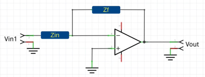
It looks like the inverting amplifier we previously saw, but this time it uses impedances instead of resistors. The amplification of this circuit can be calculated the same way as the inverting amplifier, but the formula now assume the form:

Depending on how Zf ans Zin are implemented, the behaviour of this circuit changes radically. This is the basis for building what are called active filters, which is a huge subject in the operational amplifiers theory.
Here, I will just present 3 of the most significant examples.
Example 1: The Integrator
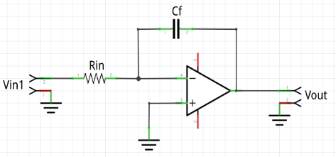
The integrator is obtained using a capacitor as the Zf and a resistor as the Zin. Its amplification is therefore dependent on the frequency and can be expressed by the following formula:

The cut-off frequency is:

As long as the frequency of the input signal is lower than the cut-off frequency, the output signal reflects the input signal, although it will be out of phase. Once the frequency of the signal approaches the cut-off frequency and goes beyond, the amplitude of the output signal becomes smaller and smaller, and that’s because the negative feedback becomes greater and greater.
This behavior can be represented in the frequency domain by a picture like this:

A circuit that behaves like this is also called a Low Pass Filter.
Example 2: The Differentiator

The differentiator works exactly the opposite way of the integrator. Zf is replaced with a resistor and Zin is replaced by a capacitor. The cut-off frequency has exactly the same formula as the integrator, but this time the behaviour is different.
When the input signal has a frequency higher than the cut-off frequency, the capacitor has a very low reactance, which translates into an output signal similar to the one in the input.
When the frequency of the input signal goes below the cut-off frequency, the capacitor has a high reactance, which translates in a lower amplification and, therefore, the signal amplitude becomes smaller.
A diagram of the output voltage as a function of the frequency shows exactly that.
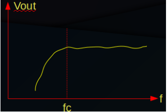
And this, of course, is the behavior of a high pass filter.
Example 3: The Band Pass Filter

If you look carefully, you will see that this circuit has both the characteristics of a low pass and a high pass filter.
R1 and C1 make the circuit behave like it was a high pass filter, but R2 and C2 make it behave like it was a low pass filter.
And in fact, if we merge the diagrams of the low pass and high pass filters we obtain something like this:

And that resembles the frequency diagram of a circuit which gives precedence to a specific frequency and attenuates everything else. This is why it is called band pass filter.
This ends the article on the operational amplifiers. Did you find it useful? Is there anything else that you would have liked to see? Was the level of the article OK with you? Please let me know in the comments.
To learn more on the topic, I also recommend to watch the video “Operational Amplifiers Explained” which also shows in practice how the circuits shown here work.

