Lights On! (part 2)


Hi there!
It is summer, and I have a number of upgrades in mind for my outdoor living areas: some involving electric upgrades, some involving gardening, some involving landscaping.
One thing I have in mind involves the night illumination of the gazebo and its surroundings. The current illumination is based on low power LED strings, powered by batteries recharged during the day by small solar panels.

However, I found that this kind of illumination has a lot of drawbacks. First of all, the lights are very dim. They are just fine when entertaining guests having conversations while enjoining the freshness of the evening air. But when it comes the time to do some table game that requires being able to look at pictures or reading stuff, often we end up going inside where we can have more light.
In addition, I need to turn on and off the lights manually, whenever I need them. If I leave them always on and let their sensors take care of the switching, they end up using the whole battery by the middle of the night and, sometimes, they take so long to recharge that by the time it is evening they don’t last that much anymore.
The solution would be to use bigger solar panes, but the batteries are still small and they also need their time to recharge. If I let them recharge too fast, they will start loosing their capability of retaining the charge too soon, and I would have to replace them relatively often. So I would trade off the usage of solar panels with more waste in exhausted batteries.

The right thigh to do, in my view, is therefore to use regular 120V lamps, obviously low power LED, but brighter than the ones I currently have. The thing is that I do like the automatism of having them turn on and off automatically from dusk to dawn. So, I thought I could design and build my own dusk to down automatic switch, which actually require just very few component and it is very cheap to make.

Schematic


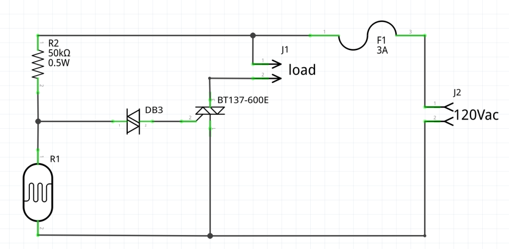
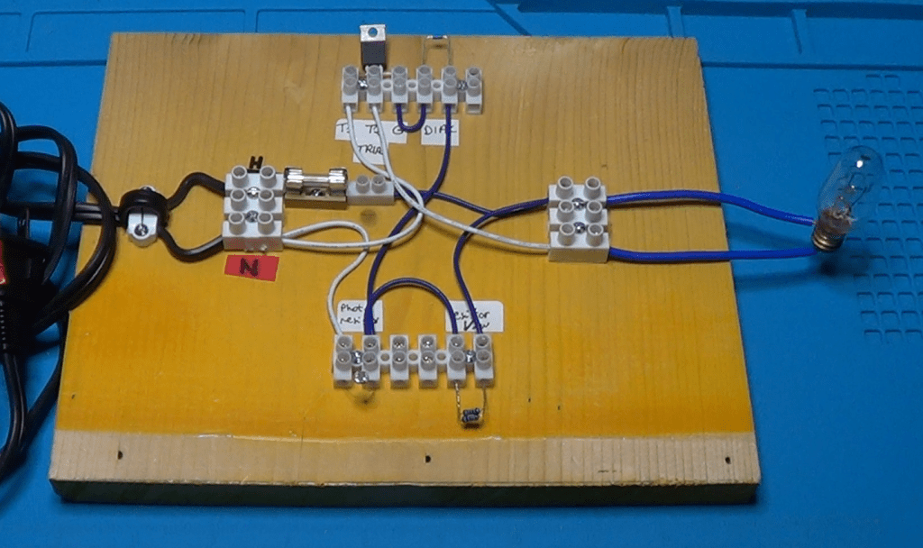
Above is the schematic of my dusk-dawn automatic switch. It is a very standard design, and it requires just a few components.
The load is basically made of the LED lamps we want to control.
The 120Vac input goes directly through a protection fuse and to the series of a 50K resistor and a photo-resistor which is the sensor that will detect the daylight condition to turn the light bulbs on and off.

When there is enough daylight, the resistance of the photo-resistor is very low, in the range between 1K and 4K. When we are getting closer to dusk, the daylight starts dimming and the resistance instead increases. Once the resistance hits the 16K threshold, the voltage at its leads goes above 30Vac.

It is at this point that the DIAC starts conducting and it triggers the TRIAC. The TRIAC, in turn, will let the current flow through the load, thus turning on the lights.
Very simple right?

When Electronics Meets Chemistry: A Conductivity Sensor For Liquid Solutions

Every now and then, my wife asks me to build a gadget that she can use in school for her demos, or for the students labs. This time she asked me for a device able to figure out if a liquid solution has low or high resistivity. Basically, if it is an ionic or covalent solution.
Here is what I put together for her in just a week-end.

Every now and then, my wife asks me to build a gadget that she can use in school for her demos, or for the students labs. This time she asked me for a device able to figure out if a liquid solution has low or high resistivity. Basically, if it is an ionic or covalent solution.

Here is what I put together for her in just a week-end.

It is a simple circuit that turns on an LED if a simple probe is put in contact with an ionic solution with relatively low resistance.

Since it needs to be portable, it is powered with a simple 9V battery.

The circuit uses an op-amp configured as a voltage follower. The output is connected to a green LED which lights up if the output goes low.

The non-inverting input is connected to the +9V through a resistor, which I calibrated empirically. Because the non-inverting input is connected to the +9V, the output will also be high and the LED will be off.

However, I can also connect the non-inverting input and the ground of the circuit to the solution through a couple of wires. If the resistance of the solution is low enough, the voltage at the non-inverting input will lean toward ground, making the op-amp output to switch to low which, in turn, will turn on the LED.

Simple enough, don’t you think?

My wife’s students will use this device to check the conductivity of a solution, to determine if the material they put in some distilled water is an ionic or covalent compound. The LED will turn on only with ionic compounds, that will decrease the resistivity of the distilled water.

For this simple device, I designed in OpenSCAD a small box to contain it. Here is the corresponding code:

$fa=0.5;
$fs=0.5;

//body
difference()
{
    cube([52, 23, 70]);
    translate([1, 1, 1]) cube([50, 21, 70]);
    translate([23, 1, -1]) cube([6, 3, 3]);
}

// cap
translate([0, 35, 0]) difference()
{
    cube([55, 26, 30]);
    translate([1, 1, 1]) cube([53.5, 24, 30]);
    translate([(55-14.5)/2, (26.5-9.5)/2, -1]) cube([14.5, 9.5, 4]);
    translate([(55-14.5)/4, 26/2, -1]) cylinder(d=5, h=4);
}

and here is a picture from the OpenSCAD preview window:

Here, instead, is a picture of the actual case:

Now a picture of the prototype mounted on a breadboard:

Testing of the device requires a small cup of plain water. We submerge the tip of the sensor (the two breaded wires) in to the cup and make sure that the LED stay off. Then we add a pinch of table salt to the water and try again. This time the LED must turn on, to signify that there is an ionic compound mixed in the water.

I mounted the circuit on a half piece of solderable breadboard.

I have chosen to cut the board in half for two reasons:

  1. The circuit is very small and does not require that much space to assemble it. Moreover, being small it will be easier to handle it with a single hand when using it in a chemistry lab.
  2. Using a solderable breadboard rather than a perfboard simplifies the wiring, because it is reduced just to some jumpers to complete the connections already available on the board.

These boards are very easy to find in online stores. I usually by mines on Amazon, but also other stores that sell electronic components have them available. Of course, you are free to use any kind of board you like, be it a simple perfboard, or a solderable breadboard, or a strip-board, or even make your own PCB.

I decided not to use the PCB because of the simplicity of the circuit. With so few components, making a PCB and put the components on it would have not saved me time, nor there was much risk of making mistakes.

Once the circuit on the board was completed, I put it inside the case I made for it, and completed the assembly with the LED and the power switch mounted on the cover. I also decided to use some tape to hold the cover on the case, considering that these little devices will be managed by students, and I don’t want them to easily open it and break it.

As an alternative, I could have used a couple of small screws to hold everything together, but this was something I had to do over a single week-end, so I decided to go through the fastest possible route for the design of the case.

My wife used the device in school right on the next day after I made it. She told me the sensor worked perfectly and her chemistry students enjoyed using it, while experimenting with different compounds to verify their nature.

All in all I am satisfied. I was able to design and build five of these devices in just a week-end, and they were all up to the expectations, of my wife of course.

If you are interested in making this device and would like to see more details on its construction, please click on the following link which will take you to my youtube video with the whole story: