Hi there, welcome back to the “Back to Basics” series.
So you’ve decided to dive into electronics. You’re watching tutorials, you’re looking at schematics, but then you hit the wall: what tools do I actually need, and where do I start without spending a fortune? That’s the biggest barrier for everyone.
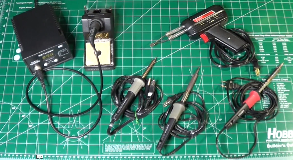
Today, we’re building your first electronics workbench. We’re going to break down the six most essential pieces of gear—from the absolute must-haves to the powerful diagnostic equipment you’ll eventually crave.
I’m structuring this into three simple tiers, to make it progressive.
Tier 1: The Must-Haves, which are the stuff you need on Day 1 to even build a circuit.
Tier 2: The Essential Builder Stuff or how to make your project permanent.
Tier 3: The Diagnostic Duo or how to troubleshoot and see signals you can’t see with your eyes. That’s for when you need to actually see the electricity doing its thing.
Let’s start building!
Tier 1 – The Absolute Must Have: The Prototyping Pair
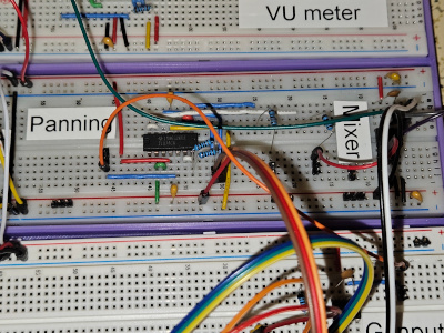
Let’s dive into tier one. The prototyping pair. First up, the breadboard, your best friend for starting out. It’s basically a temporary solder-less lab.
It will let you try things out, make mistakes, swap components. Basically: super fast iteration.
The key thing to get, though, is how it’s wired internally. Those middle columns, they connect vertically. Little strips of metal inside. You plug your component legs into different rows in the same column, and they’re connected.
Those long strips on the sides, the power rails, run horizontally all the way from left to right. Knowing that difference saves hours of confusion. So vertical columns for components in the middle, horizontal rows for power on the sides. Simple when you know it.
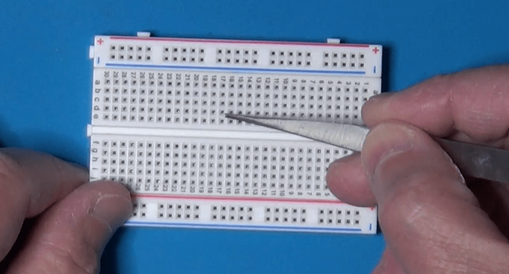
Once you’ve built something, you need to check if it actually works or why it doesn’t. Which brings us to the second must-have in Tier 1, the digital multimeter, or DMM. The Swiss Army Knife. You just can’t debug what you can’t measure. It’s fundamental. Safety, too. Measures voltage, current, resistance, the basics.
Tier 2 – The Essential Builder: Permanent Connections
Let’s now move on to Tier 2, the essential builder.
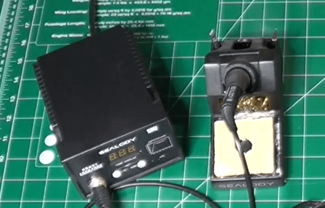
So your breadboard circuit works perfectly. Awesome. But now you want to make it permanent. Put it on a proper PCB or maybe a perf board. And that means soldering. You need a soldering iron and you need solder. This is where things get hands on. But what iron to use? There’s so many types.
The key thing is temperature control. You need to be able to set the right temperature for your soldering components. Too cold, and you obtain bad joints. Too hot, and you damage the components.
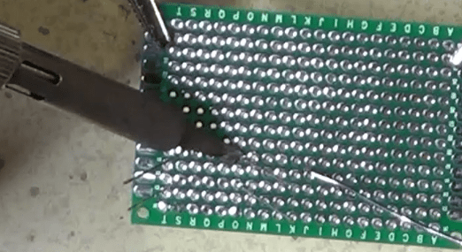
And then you need the proper technique. This is where people often mess up, big time. The absolute number one rule is: melt the solder with the components to attach together, not with the solder tip. You touch the hot iron tip to both the component leg and the copper pad on the board at the same time. You hold it there for a couple of seconds, just long enough for them both to get hot. Then you touch the solder wire to the joint, not to the iron tip. And the heat from the pad and the leg melts the solder, making it flow nicely around them. You’re aiming for that classic shiny volcano shape, a little cone. Not a dull blob. Definitely not a dull blob. Dull or lumpy means a cold joint, which will probably fail later.
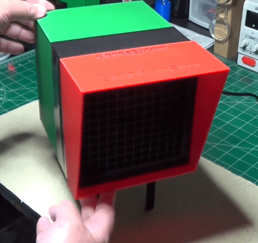
Also, always use a fan or work in a well-ventilated area. Those fumes aren’t good for you.
Tier 3 – The Diagnostic Duo: Seeing The Unseen
Now tier three, the diagnostic duo. This sounds more serious. Well, it is, in a way. This is for when you move beyond simple DC circuits into things that change over time, like audio signals or digital clocks.
First in the list is the function generator, or the signal injector. Its job is basically to create predictable electrical signals.
Known, clean waveforms, usually sine waves for analog stuff, square waves for digital, maybe triangle waves for ramps. Why is that necessary? Can’t you just use the signal from, say, the phone’s headphone jack? You could, but is that signal perfectly clean? Does it have noise? Is its amplitude exactly what you think? A function generator gives you a reliable, known-good input. So you’re eliminating unknown variables.
If you test a filter circuit with a perfect sine wave from the generator and the output looks wrong… Then you know the problem is in your circuit, not just some garbage coming in. It’s about controlled testing.
And now the function generator partner, the oscilloscope. The big gun. This is arguably the most powerful debugging tool in electronics. It lets you see electricity.
It draws a graph. Voltage on the vertical axis, time on the horizontal. So you can see exactly how a signal changes, millisecond by millisecond or even faster. So you can see noise, distortion, timing glitches. Things way too fast for a DMM.
And the key to using it effectively, the thing that unlocks its power, is the trigger control. It just tells the scope when to start drawing the waveform on the screen.
It looks for a specific voltage level on the signal. So every time the signal hits, say, one volt while rising, the scope starts drawing from that exact point. And because it starts drawing at the same point on the waveform over and over, that fast-moving signal looks like it’s standing perfectly still on the screen. Makes analysis possible.
So you hook the function generator output, like a 1 kHz sine wave, to your circuit input and then probe the output with the oscilloscope. And you can see precisely how your circuit affects that signal, stable and clear, thanks to the trigger. That’s how professionals diagnose high-speed problems.
Conclusion
Let’s recap quickly, by function.
Tier 1, the must-haves for prototyping are the breadboard and the DMM.
Tier 2, the essential builder for making it permanent, is the soldering iron and the solder. And don’t forget the ventilation!
Tier 3, the diagnostic duo for seeing the unseen signals, are the function generator and the oscilloscope.
That’s the core toolkit for your lab.
The really crucial takeaway is that you don’t need everything on day one. It’s scalable.
Start with Tier 1. Get comfortable prototyping. Then, when your projects demand permanence, you move to Tier 2.
And only when you’re dealing with signals where timing and shape really matter, like building an audio filter or maybe something with a micro-controller, you invest in Tier 3 for that deeper diagnostic view.
Start small, build your skills, and let your projects guide how you grow your lab. Build it organically.
You don’t need everything at once!
Finally, here is the link to the companion YouTube Video, which you may want to watch for additional details.
Welcome to the first part of the new series Back-to-Basics, where we will explore everything electronic, from the simple components to the more complex ones, and where we will learn how to create our own circuits and make sure they are safely working.
Why Safety?
Electricity is dangerous! Whenever working on a circuit, even if powered with batteries, always be careful and pay attention on what you do. Always pay attention to safety. You could cause an explosion, start a fire, get burned, even get some shrapnel in the eyes if not careful.
In the end, you need to work safely for a number of reasons:
To protect the environment where you work
To protect the devices which you use while working
To protect yourself
To protect the electronic components you use in your projects
Let’s dig a little deeper into these points.
The Foundation
Whenever you work on an electronic device, it is always better to power it down, whether it uses batteries or the grid power. Always disconnect power before working on a circuit. And if you are not sure whether a circuit is powered or not, just use a multimeter and check it out.
The only case where you should work on a powered up circuit, is when you have to test internal functionalities to verify whether it works fine or not. Even then, you should take precautions to avoid causing short circuits, o touching parts where dangerous voltages are present.
Make also sure to have a good ventilation in the work place, especially when soldering or dealing with chemicals to make PCBs. When the ventilation is limited, make sure to have around some sort of good air filtering system, like this one to absorb the soldering smokes:
or this one to keep the whole room odorless and with clean air:
To avoid unpredictable and useless hazards, always keep your workbench clean from clutter. Only put on it what you really need and try to be well organized.
And remember: food and drinks are not among the necessary items on your workbench. Besides the risks of spilling liquids on electronic circuits, never touch food after handling electronic circuit, especially if soldering is done with a tin-led compound. Keep food away and wash your hands immediately once you leave your lab area, even if it’s done for only a few minutes.
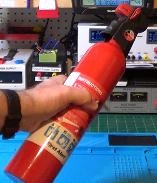
Finally, just for those unpredictable moments, always keep around a small fire extinguisher, like this one:
as well as a first aid kit and a list of phone numbers to call in case of an emergency.
Protect yourself
Although workplace safety is important, it is also important to not underestimate personal safety. Especially when working in certain conditions, it is important to wear personal protective equipment, or PPE.
When the conditions suggest that, it is appropriate to wear safety goggles or glasses to protect your own eyes from sprays of melted solder, flying wire clippings, or chemical splashes, for example while etching a PCB.
Insulated gloves become useful when working with high voltages, like the voltage coming from a power outlet.
And it is also important to always wear shoes that have an insulating sole, so you are not electrically connected to ground when handling such high voltages. And, even if you are not dealing with high voltages, it could still be useful to prevent, for example, sending high impedance signals to ground when touching a circuit under test, or something similar. Sitting on a wooden stool also helps in staying insulated from ground.
But, obviously, there are circumstances where you actually want to be connected to ground, although never directly but through a relatively high resistance, for example when working on components sensitive to electrostatic charges. We’ll talk more about that particular case later.
Finally, for your own safety, it is also useful to avoid certain kind of clothes that could be too loose and could snag around anything on your workbench or, worst, conduct electricity. And, especially for that, absolutely do not wear any piece of jewelry that can touch anything that has an applied voltage and cause, possibly, a short circuit or, worst, close the circuit through your body.
Save your components
Let’s now talk a little bit about components safety. And, besides the usual talks about burning components with the iron solder or break their leads, or similar other stuff, I would like to talk about a subject that is often underrated: Electrostatic Discharge protection, or ESD protection.
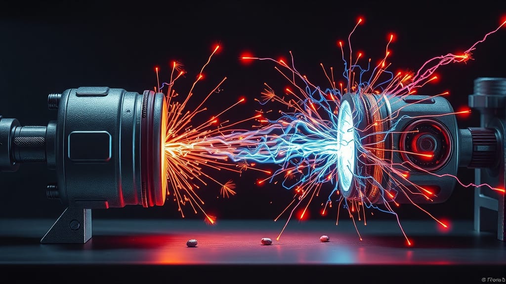
I’m sure you have probably experienced static electricity several times in your life, for example when touching a door knob right after walking over a thick carpet in an environment with low humidity. Did you ever experienced a painful shock, while doing that? Or sometimes just touching another person in the same conditions, or maybe coming down from a vehicle and getting shocked while touching the metal of the door.
All of them are forms of ESD. ESD is nothing other than the sudden flow of charges between two objects, that build up opposing charges and found themselves at two different electric potentials. When such objects come into contact, or maybe just when they are close enough to each other, the charges start moving from one object to the other to reach an equilibrium, and that creates a sudden and brief current.
The problem with ESD is that while it causes just some discomfort to us, it can cause catastrophic effects to certain electronic components. And the worst thing is that we feel such discharges only if the voltages are very high, but static voltages of just hundreds of volts, or a few thousand of volts are totally unobservable to us, but they can still cause a lot of damage to electronic components, especially those based on MOS technology.
We could be charged enough to break a component as soon as we touch it, but not enough to feel the effect of the discharge. In such a case, we would move on using the component and then the whole circuit does not work or works erratically, depending on the amount of damage on the component. Integrated circuits are the most affected, because the discharge can break part of them, but the reminder works perfectly, thus causing the erratic behavior.
And that’s why understanding and preventing ESD is so crucial when handling electronic components.
So, how can we avoid such problems?
The trick is to make sure that everything on your workbench is charged to the same potential, and it is even better if that potential is the one of ground. Should you then connect yourself to ground with a wire to avoid ESD? No, and for two reasons. First, if we connect ourselves to ground, we violate one of the previous rules on our own safety. Second, if a component is electrically charged and we touch it while connected to ground, we cause right there an ESD event that could destroy the component.
Then… what do we do?
We use high value resistors. High enough not to connect us directly to ground, but small enough to allow the extra charges that may accumulate somewhere to slowly discharge toward ground without causing any damage. And we do the same with the workbench surface.
But how? We are talking about surfaces here: the one of the workbench and the one of our body. How do we connect a resistor to a surface?
We don’t. Instead, we make the whole surface itself a resistor and we connect a corner of it to ground, leaving everything else, the other end, ready to discharge any voltage that may come close to it.
This is done with wrist straps that we can wear:
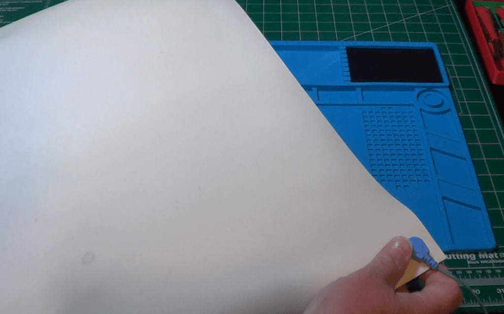
and it is done with ESD mats:
which we lay on top of the workbench surface when we need to work on something that need ESD protection.
The wrist strap ends with a wire that can easily be connected to ground. It has also an internal resistor, usually 1M, to make sure we are not directly connected to ground, for our safeguard, and the safeguard of the sensitive components.
Similarly, the ESD mats can be lay down on the workbench and their wire can be connected to ground, making sure that there won’t be any accumulation of charges on the workbench.
The ESD mats are made of a material that offers a certain amount of resistivity , so that the ESD can happen without causing dangerous currents.
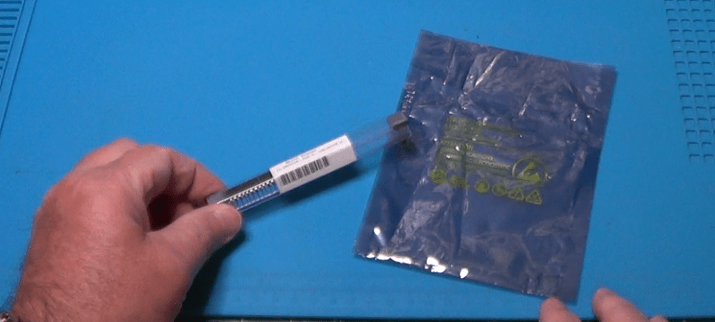
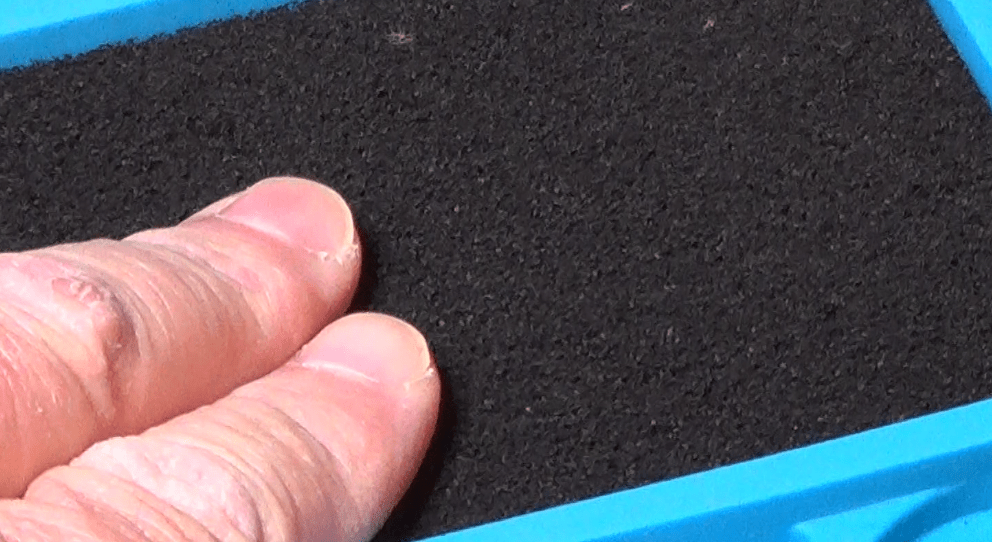
But it’s not all. Don’t think that using a wrist strap and an ESD mat is enough for protecting sensitive components. You also need to store them in a safe place, a place where they cannot be reached by electrostatic charges.
The concept is the same: you wrap them in a resistive material that prevents charges to accumulate on itself, and that prevents those charges that still contaminate it to reach the wrapped component.
Welcome to the anti-static bags and containers and to the anti-static foam, both made of plastic mixed usually with graphite, which guarantees a certain resistivity, not too low, not too high.
Tool-specific safety
Another important aspect of lab safety is related to the correct handling of the instruments we all use.
And the first one I would like to mention is the soldering iron, which we all use to connect components to a PCB, or to each other.
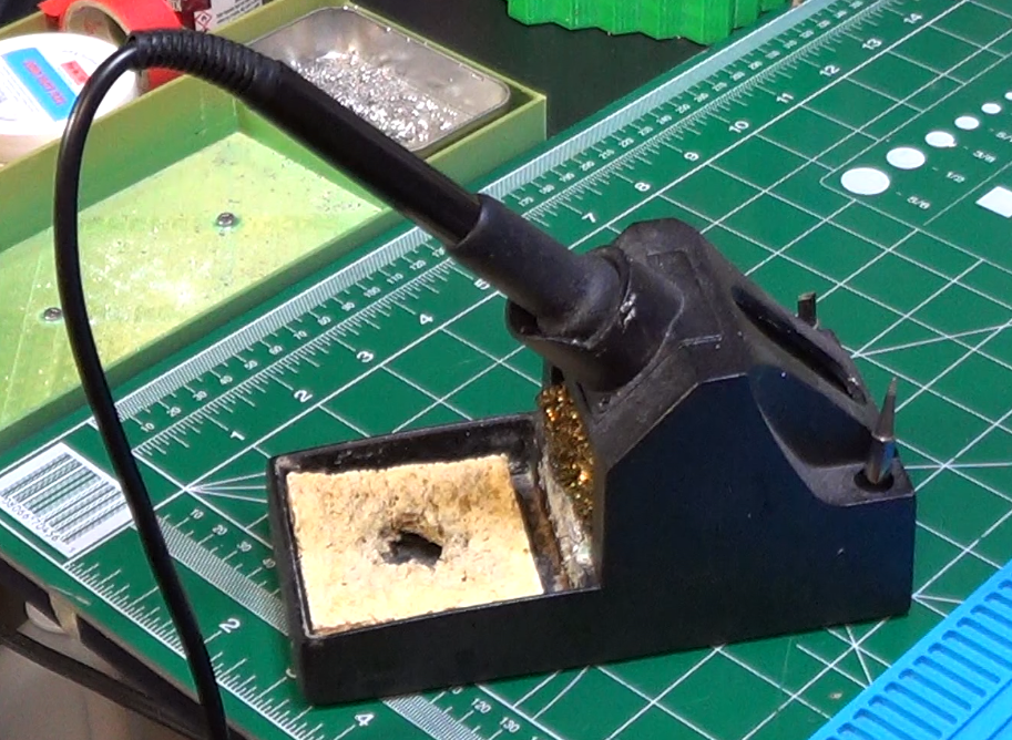
Whenever the soldering iron is on but not being used, make sure you put it on its stand.
These stands are usually made of metal, or at least the part that is in touch with the soldering iron is made on metal, capable to resist to the temperature of the iron itself. Putting the soldering iron directly on the workbench is not a safe thing to do. It can inadvertently touch something and melt it or burn it. It can fall on the floor, it can land on your lap burning you. So, always keep the soldering iron on the stand when not in use.
Another important thing is to keep the tip of the soldering iron perfectly clean. It is clean when it is covered with a thin layer of solder. The solder covering the tip allows it to better transfer its heat to the components and thus have less chances of making bad soldering points.
Whenever the tip gets dirty, it should be cleaned thoroughly. Never try to clean it with abrasive objects, like a file or sand paper. If you do that, you may risk of ruining the underlining protection of the tip, which will then not be able to work well anymore.
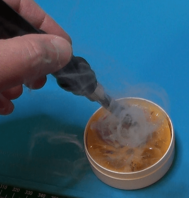
To clean the tip, I usually use some rosin paste. I heat the soldering iron and i submerge the tip into the paste for a few seconds. Then I remove it from the hot bath and I clean it with a cotton rag. Please do not use rugs made of synthetic material because that could melt onto the hot tip and ruin it.
Once done that, if there is not enough solder left on the tip, just melt some on the tip and then clean it again with the rug. Keep doing that until it starts shining.
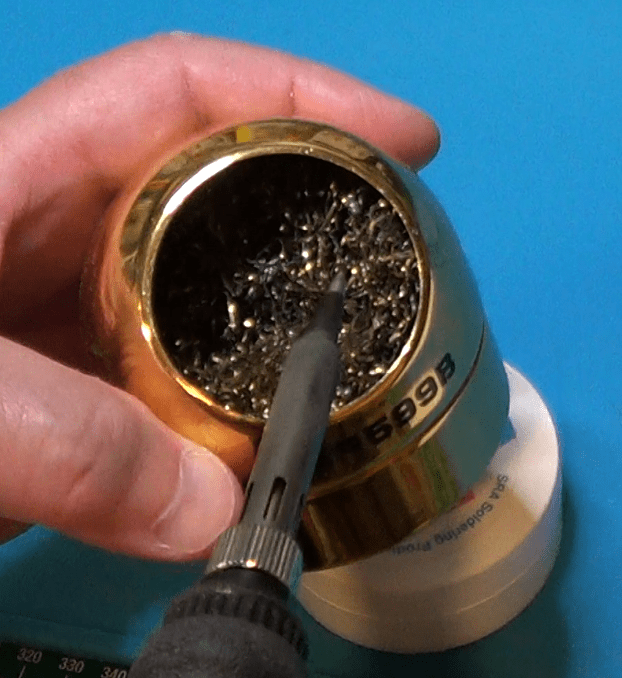
Even while you solder you should clean the tip every now and then. To do that, you can just scrape the excess solder using one of these cleaning sponges made of copper wire.
Alternatively, you can use a real sponge kept humid, and not totally wet, to brush the tip clean.
Between the two, the one I prefer is the copper wire sponge, as the actual sponge tend to lower the tip temperature for a few seconds.
And of course, while you solder, try to avoid breathing the smoke. If you can, use a fume extractor. Otherwise try to at least ventilate the room, or use an air filtering system set to its max.
Now, I know I shouldn’t tell you that, since it is obvious. However, I feel it is always better to be safe that sorry. So, here it is: please never touch the tip of the soldering iron when it is on, even if you think is not that hot.
Finally, always, after each soldering session, please wash your hands thoroughly, especially if you use a lead-based soldering wire. The lead of such wires will not evaporate and you will not breath it, but lead residues can remain on your fingertips and you can later ingest them.
Soldering fumes do not contain lead, only rosin. There is not enough heat to make the lead evaporate. Just avoid breathing the fumes because they smell bad and you might be particularly sensitive and start coughing. Plus, rosin has really an acid-like smell which you may want to avoid breathing.
Let’s now talk about another lab device that we want to keep safe: the multimeter.
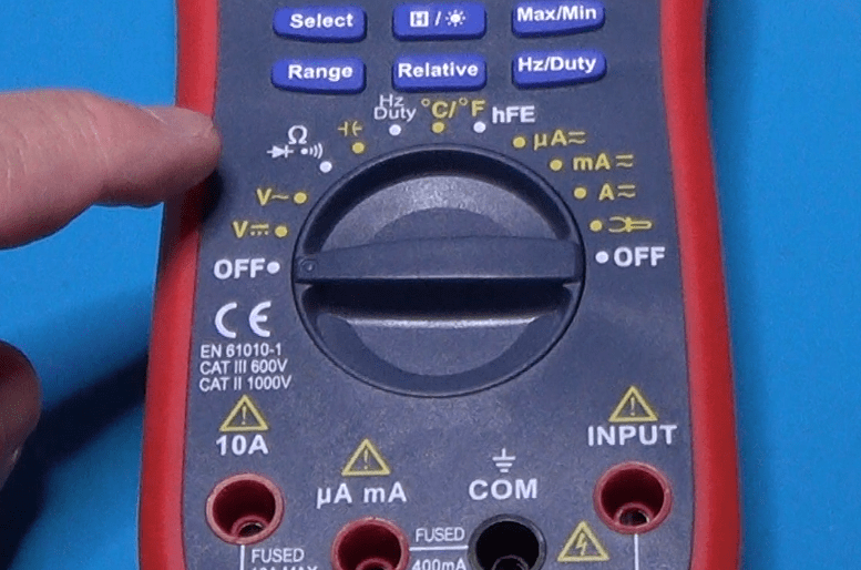
First, let me point out what is called the “category rating” or simply cat rating.
The cat rating is usually indicated on the instrument itself. This one, for example, is certified for both category 2 and category 3.
But what does that mean?
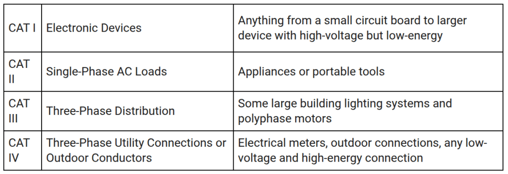
Category levels let us know the maximum rating of an instrument, according to this table.
Additionally, the category of an instrument also specifies the transient conditions under which an instrument should be used. That is because transient conditions allow for higher voltage measurements, but only for very short period of times.
This table provides, for each category, the max continuous voltage and the transient voltage, as well as the internal impedance of the energy source.
So, for example, a cat 2 instrument certified to work at up to 600V, is supposed to be able to handle transients up to 4000V.
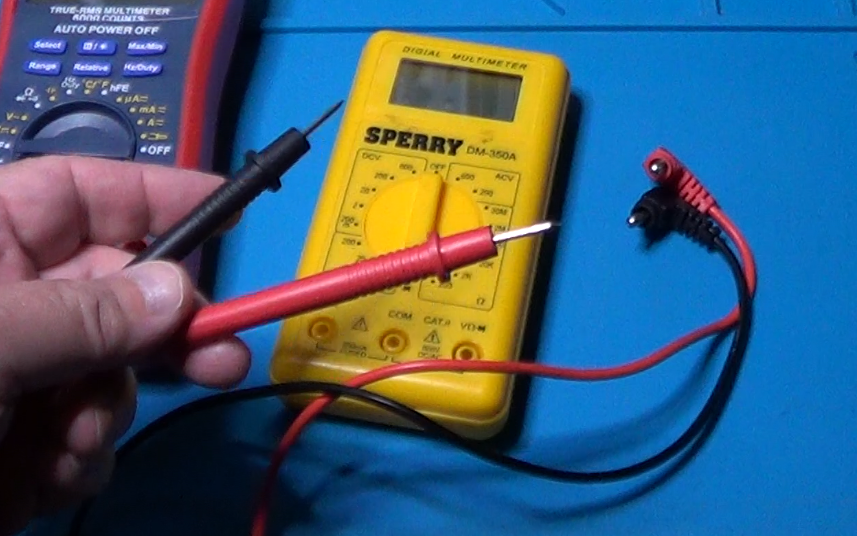
And here are the typical probes used with a multimeter:
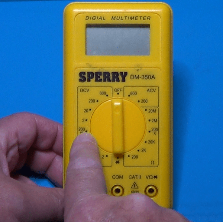
To avoid breaking the multimeter you are using, it is also important to set it appropriately for the measurement you need to perform.
At least, you will have to set the measurement unit that you need and the device will take care automatically to select the most appropriate range.
For totally manual instruments, however, you will have to select not only the measurement unit, but also the range.
Be careful when doing so. Multimeters can break. Always set a range higher than the max value you expect to measure. If you don’t know what the max value could be, start with the highest setting, and then lower them one step at a time until you reach the lower possible range that is still higher than your max value.
And finally, before using the probes, make sure they are fine. Check especially for any breakage in the wires insulation. You don’t want to get an electric shock inadvertently.
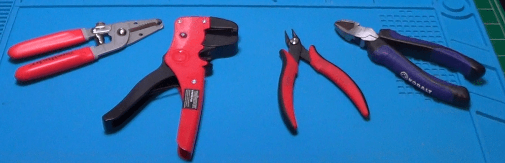
Another tool category we need to talk about is the one of wire strippers and cutters. They seem to be simple tools to use but an improper use of them may lead to frustrating mistakes, and can even damage components or cause injuries.
There are different types of cutters and strippers for different tasks. Here are some examples. Using the wrong one for the task being performed can become a major hassle.
The standard stripper has usually multiple holes of different sizes. To use it properly, you must match the hole size with the wire gauge.
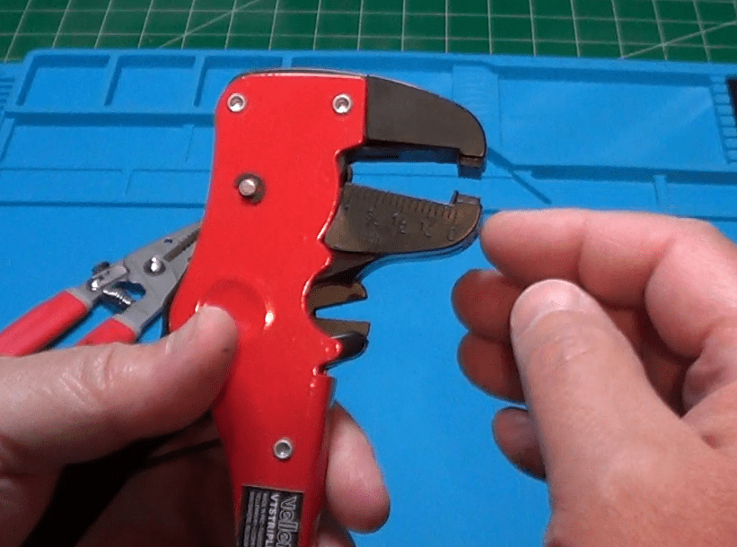
A self adjusting stripper is less precise than the standard one, but it is better suited for bigger cables like, for example this coax cable.
Using the most appropriate stripper for the job will prevent you from accidentally nicking or even cutting strands of wire, which can later weaken the connections and possibly cause a break during operations.
Here are a few examples of wire cutters.
A flush cutter like this is very useful to cut small wires, and it is perfect for cutting that extra length of component leads after they have been soldered to a board.
A diagonal cutter is definitively more robust than a flush cutter and it is more suited for thick wires or whenever a perfectly flush cut is not required.
And of course, you may also have a combination tool. This wire stripper, in fact, can be also used as a wire cutter.
Always try to match the size of the wire with the size of the stripper or the cutter. This will avoid nicking a solid wire or cutting a few thin strands of a multi-strand wire. These events always weaken the wire making it prone to breakage under use.
Always cut away from yourself and possibly wear safety glasses to prevent flying clipping to get into your eyes.
Store these tools in such a way that the blades are protected from hitting other metallic tools that could damage them.
And, finally, never use an inappropriately small cutter to cut thick wires. The blade could get damaged.
The last category of tools I would like to mention is the one of power supply units. Most of us have at least one of these unit on the workbench. They come very useful when we need to power up a circuit we just made so we can test it.
When doing so, always make sure to connect the cables using the correct polarity. Using colored cables make this much more easier.
Be careful when using a variable power supply. Always double check that you have set the right voltage. Be aware that power supply units have fuses that can trip when the power you are using is above the limits of the unit. And some devices, even give you the possibility of regulating the max current that can be erogated. In that case, be careful not to set it too low, or the voltage will decrease when the current increases. Also, do not set the max current to a value too high, or the power supply unit will not lower the voltage if the power absorbed by the circuit under test becomes too high.
Finally, pay attention to never short the outputs of the power supply. It might cause sparks, it might burn the insulation of the cables, and it might even cause a fire.
Working with AC power
And now, just a few words of caution when dealing with circuits that are powered through a house outlet.
Please, please, please: working with AC mains voltage is extremely dangerous and should only be done either by experienced individuals or by their direct supervision.
Don’t do like myself that, when I was very young, I tried to power my HO train directly from the power outlet, (electric spark noise) burning the locomotive motor, and blackening the wall around the outlet. I am very lucky to be still here and be able to tell this story.
Best practices
In general, when working with electricity and with electric or electronic devices, be always careful. Try to foresee what could happen before you do something. Read the manuals of the equipment you use and understand their capabilities and limitations.
Always double check all the connection before powering up. If you can use lower voltages before providing the full power to the device under test, please do so: start with a lower voltage and then increase slowly, so you will be able to notice any potentially dangerous activity.
Never be in a rush when working on your workbench. Rush is the mother of the worst mistakes. Don’t let rush to overpower you.
Finally, when in doubt, don’t be ashamed to ask somebody else more expert than you. Nobody knows it all.
Conclusion
Sorry if I annoyed you with all this talk, but I believe this was a necessary start of the new series on electronics basics. From now on, I will try my best not to bore you anymore. Instead, we will dive into the world of electronics examining components, designing circuits together, experimenting with fun stuff, and more.
I have a long list of subjects ready for you, and I’m sure you will enjoy all future posts in this series.
Short guide to choose the right multimeter for your needs.
The very first instrument that an hobbyist buys for the electronics lab is the Multimeter. There are several choices in the market and it is very difficult to make the right decision.
Sometimes it is the amount of available money that forces our hand when choosing the instrument, and sometimes the inexperience drive us to make the wrong judgement.
In this article I will try to provide a set of useful information that will help you make an informed decision. But, always remember that the cheapest solution is not always really the cheapest one. When you are uncertain between a couple of models, always choose the one with the best features. That will avoid future regrets, the moment you realize that the missing features where those that you needed the most. Making the wrong choice may force you, later on, to buy a second instrument because you realize the one you got does not satisfy your needs.
Let’s start with the first categorization: analog versus digital.
In this era of digital devices permeating the market in all electronics categories, the choice of buying a digital multimeter seems obvious. But is it? We need to explore a number of properties and features of both kind o devices. Only after you know pros and cons of each, you will be able to make a decision based on what you envision being the usage that you’ll make with the instrument. And, sometimes, you’ll find that having both kind of instruments is better that having only one.
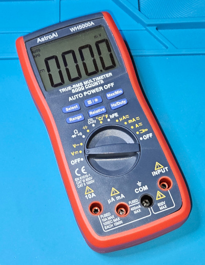
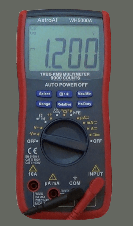
A digital instrument is definitively easy to read, especially if it has a large display, and it is even better if it tells you the measurement unit along with the value, like in the one depicted on the left. On the other end, to be able to show you a number, the digital instrument needs to make an analog to digital conversion, which takes time to complete. After all the quantity under measurement is always an analog one.
The problem with the analog to digital conversion is that it takes time; it is not instantaneous. As a result, if you are measuring a quantity that slowly changes over time, you could end up with a situation where the quantity changes before the instrument has completed the conversion. In such a case, you would not be able to see any useful reading on the display. The numbers would keep change continuously and inconsistently.
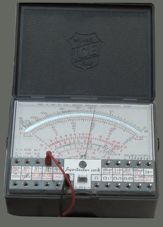
An analog instrument, on the other end, is not that easy to read. Depending on the type of measurement you have to make, and how big is the value under measurement, you will have to find on the display the right scale to use, and that can be confusing, sometimes. The good thing about this instrument, however, is the fact that the needle always responds instantaneously to the quantity being measured.
It might take some time for the needle to reach the right position on the scale, because of its inertia. But that same inertia allows the needle to find itself an average of the value if the quantity is slowly changing over time. Not that the measurement will be precise. It will not, but it will give you an idea of what is going on, while with the digital instrument, you would just see a bunch of numbers continuously changing in a pseudo random way.
Is then the analog instrument better than the digital? Well, wait a minute here. There are still several parameters to evaluate.
Let’s talk about precision. Both digital and analog instruments can have a pretty good precision, but with the analog instrument sometimes you have to guess the best reading, because the needle is not exactly on a mark on the scale, but is instead in between two marks. And things get even worst when accounting for the parallax error. When you look at the mark underneath the needle, depending on the position of your eyes compared to the needle itself and the scale, you may find that moving your head a little bit on one side or the other, the measurement changes. And that’s why the best analog instruments have a mirror on the display. If you look at the needle with one eye only and you position yourself in such a way that you don’t see the reflection of the needle on the mirror, then you are perfectly vertical on top of the needle and you can make a better measurement. And of course this takes time, usually more time than taking a measurement with a digital instrument. Digital instruments, on the other way, may have the precision of just a couple of digits or more. The more the better of course. For a decent lab instrument, you may want to go with instruments, either digital or analog, where you can make a read of at least 3 digits, better 4.
And after all the effort to make a good measurement, you could find yourself with a perfectly useless measure. Why? Because of the impedance that the multimeter puts in parallel to the points under test. And this bring us to yet another difference between analog and digital multimeters.
The majority of analog multimeters present a low input impedance, which means that they draw a certain amount of current from the test points. And this extra current could cause an extra drop of voltage across another resistor that is part of the device under test. The result would be that the reading looses accuracy.
A digital instrument, on the other end, usually has a very high input impedance, in the order of several mega-ohms, compared to the tens of kilo-ohms of the analog instruments. Just because of that, measurements taken with a digital multimeter are usually more accurate.
But then, that is not always true. There are analog multimeters that are equipped with an amplification stage with FET or MOSFET. Those analog multimeters have an input impedance comparable to the one of the digital instruments. Always read the specs of the device you are buying and try to figure out if the input impedance is in the order of the kilo- or mega-ohms. The higher the better.
To conclude, to make the right choice when buying an instrument, normally go with a digital one, unless you already know that the majority of readings you will ever make will be done on slowly changing values. Buy always an instrument that gives you the best precision you can afford, with the highest input impedance. And keep in mind that for a multimeter to be useful in an electronic lab, you want to be able to measure magnitudes very small but not necessarily that high. Shoot for an instrument that will make you read micro-amps and milli-volts, for example.
Last, if you can afford it, you could buy both a digital and an analog instrument. Analog instruments are cheap nowadays, and can be easily found also in the second hand market, like on eBay. And once you have a decent analog instrument, you don’t have necessarily shell a lot of money on a digital instrument. There are decent digital multimeters below the one hundred dollars value. Take a look at the Merchandise section of this web site for such an instrument.
If you would like to know more on this topic, and see both the analog and digital multimeters in action, I suggest you to watch this Youtube video.