Hi there! Welcome to the fourth episode of Back To Basics, where we explore everything electronics from the beginning.
It is time to start learning about components, and what’s better than beginning with the ubiquitous resistor, a component present in each and every electronic circuit.
We will cover some theory, the math, and the major kind of resistors available on the market. All with a very simple approach that will help you understand what resistors are for, and which one to choose for your own projects and experiments.
Controlling The Flow
Before we get to the components, let’s look at the three ways materials behave electrically.
There are three fundamental kind of materials:
- conductors,
- insulators, and
- resistors
Conductors allow current to flow very easily, like for example in copper wires. They have a high conductivity, which translates in a very low resistance.
Insulators are the opposite of conductors. They block the current flow, like for example with rubber or plastic. They have a very low conductivity, which translates in a very high resistance.
In between these two categories we have the resistors, which are capable of controlling the current flow. They lay in between the conductors and the insulators in terms of conductivity, having very specific values of resistance.
You can view resistance like a water pipe. Conductors are very large water pipes, which offer minimal resistance to the flow of water, here representing the electric current.

Insulators are totally clogged pipes, where the flow of water is totally stopped.

And finally the resistors, which are like water pipe of a specific section, so that they limit the flow of water to specified amounts.

The Fundamental Rule: Ohm’s Law
The math that governs the current flow through a resistor is called Ohm’s Law, and it is the most important concept in electronics.
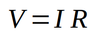
Here is the formula:
V = I R
where:
V is the voltage, or the entity that forces the current to flow, which is measured in Volt; I is the current, or the flow rate of the charges, which is measured in Ampere; R is the value of the resistance, or the entity that opposes to the flow of current, which is measured in Ohm.
Resistor Calculations: Series And Parallel
Most of the time we need to create circuits with multiple resistances, connected in various ways. Two most common ways of connecting components are the series connection and the parallel connection.In both case, resistors can be replaced with an equivalent resistance.
Here is an example of two resistors, R1 and R2, connected in series. When resistors are connected this way, there is only one path for the current and the equivalent resistance R3 is just the sum of the resistances in series.

And here is an example of two resistors connected in parallel. In such cases, the current splits into multiple paths when it enters the parallel, and it regroups when it leaves the parallel. The equivalent resistance is the reciprocal of the sum of the individual reciprocal resistances.

Note the simplified formula on the right, only valid in the case of only two resistances in parallel.
You can see that when resistors are in series, the total resistance increases, while when the resistors are in parallel, the total resistance is smaller that the smaller resistor in the parallel connection.
Practical Example
Let’s put this information into practice.
Let’s say we have a 9V battery, a resistor, and a LED. Knowing that the current that must flow through the LED is 20mA, and that the voltage at the LED is 2V, what’s value of resistor we have to put in series to the LED to limit the current to the 20mA value?
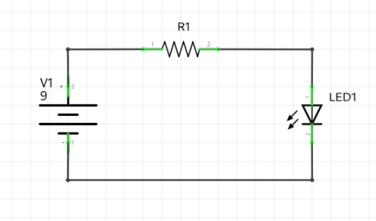
Since the three components are all in series, the current will be the same through all of them. Since we want a 20mA current through the LED, then also the resistor will be traversed by a current of 20mA. Additionally, the volt at the resistor is given by the difference between the voltage value on the left and the one on the right. The voltage on the left is the battery voltage. The voltage on the right is the voltage required by LED, which is 2V.
Using Ohm’s law, we can therefore write:

So, in practice, if we want to power an LED using a voltage source of 9V, we need to put a resistor in series with a value of 350 Ohm.
Physical Components: Types Of Resistors
Let’s now take a look at the kind of resistors we can find on the market and how they are made.
We have two main categories based on the physical aspect of the resistors:
- through hole resistors, or THT resistors, usually in the shape of a cylinder with two wires coming out of them, and
- surface mounted resistors, or SMT (or SMD) resistors, usually in a cubic and small shape.
We can also categorize resistors as fixed or variable. All fixed resistors can be either THT of SMD resistors. The variable resistors can be mechanically variable, thermally variable, or electromagnetically variable.
A typical example of mechanically variable resistors are the potentiometers, which usually have three terminals, the usual two at their two ends, and a third one, connected to a sliding connector touching the resistive material between the two ends. Measuring between one of the two end terminals and the slider, we can obtain all the resistance values between zero and the nominal value of the potentiometer.

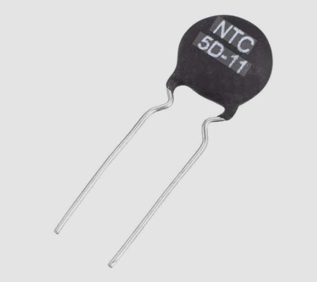
Thermally variable resistors are usually called thermistors. They have two leads, and their resistance value changes with the temperature.
An example of electromagnetically variable resistor is the photo-resistor, a resistor that changes its resistance with the intensity of the light.

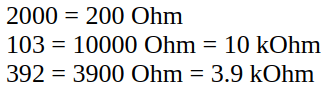
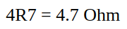
The resistance value of resistors can be imprinted on the resistor itself in two different ways, depending on the kind of resistor. It can be just printed using only numbers, the last of which always represents the number of zeros following the other numbers. Or it can be printed using numbers and the letter R, which represents the decimal point. Or it can be imprinted in the form of colored bands.
Here are a few of examples of number representations:
And here is an example with numbers with a decimal point:
When using colors, instead, we can have from a minimum of 3 bands, to a maximum of 6.
Here is the decoding chart to interpret the resistance value, the tolerance and, eventually, other information. You can find similar charts with a simple google search.

One last classification of resistors is based on the material used to make them. We can have:
- carbon film resistors, made depositing a thin layer of carbon, usually graphite, on a ceramic or paper substrate
- metal film resistors, made of a thin layer of metal deposited on a cylindrical support
The final, but not the least important, specification about resistors is their power dissipation capability or power rating. The power rating depends on the type of material they are made and the type of material of their support, as well as their size and the presence of a aluminum heat sink. the numbers can vary from 1/8W, going to 1/4W, 1/2W, 1W, and so forth, up to the hundreds of Watt.
When calculating the value of a resistor, never forget to calculate also the power it will need to dissipate, and always choose a resistor that can dissipate at least that amount of power.
For example, let’s get back to our example of resistor limiting the current in a LED. To calculate the power dissipation, we can use either one of these formulas:

n our example, we know the value of the resistor and the current that flows through it, so we can write:
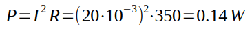
Therefore we can use a resistor capable of dissipating 1/8W, equal to 0.25W, since its rating is greater than the actual dissipated power.
Don’t forget: always use a resistor with a rating higher than the calculated power, or the component may burn or even explode.
Conclusion
Well, now you know the theory behind resistance, how to use Ohm’s Law, how to calculate series and parallel equivalents, and how to physically identify the component you need.
In the next episode, we will dive deeper into the Kirchhoff’s Laws, which build on top of everything we covered today.
Happy experiments!!!
By the way: here is the link to the corresponding YouTube video, which you may want to watch for completeness: