Presenting the block diagram of the Theremin we are going to build in this series.

The Theremin is one of those devices that was created by chance, while looking for something completely different.
Leon Theremin, which was studying the design of the early proximity detectors for the Russian government, discovered that his invention could be adapted and used for a totally different scope. The Etherphone was born.
Later on, once the instrument became well known and was produced under several different names by RCA first and other brand names later, it became commonly known under the name of its inventor, Theremin himself.
The concept of the Theremin is today easily understood as a device that uses the beat between two very close high frequencies to produce an audible frequency.
There are several ways to implement the device, although they are all variations of the same base design used by Leon. Since I wanted to create my own version of it, and since I wanted it to be a real musical instrument, I did some research and came up with my own version of the Theremin schematics. In doing so, I put together an instrument with the same features as the original Etherphone, along with enhancements that can be found in today’s commercial versions.
I present today the block diagram of my version of the Theremin. In future articles I will dive into the details of each of the blocks and how they can be practically built, also with the aid of videos that I will publish on my YouTube channel.
Starting at the center left, there is a reference oscillator for the pitch. The frequency is adjustable in a narrow range to allow the tuning of the instrument, which is heavily dependent on the physical features of the person that plays it (more on that, later).
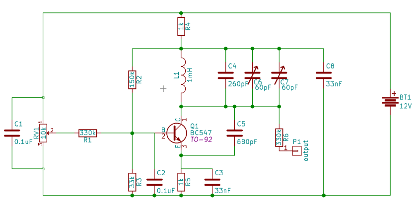
On the top left, you can see a second oscillator. The frequency of it can be modified by the distance of the player’s hand from the pitch antenna. The player’s hand and the antenna are capacitively coupled. Changing the distance of the hand from the antenna, changes the capacity, thus changing the oscillation frequency. Since the capacity is affected also by the size of the hand, the humidity of the air, the distance of the antenna from the body of the musician, and several other factors, the reference oscillator frequency needs to be adjusted before being able to play the instrument, to make sure that the range of notes generated by the Theremin is within the optimal range for the music that will be played.
The output of the pitch reference oscillator and the variable oscillator are mixed together in the box labeled “mixer”. In there, the two frequencies beat and produce two more frequencies, one being the sum of the two, and the other one being the difference. The mixer output these signals after passing them through a low-pass filter, which eliminates the higher frequency, leaving only the lower one, which is the difference of the frequencies of the two oscillators. When the signals from the two oscillators have a close frequency, the produced difference beat becomes an audible frequency, the music generated by the Theremin.
The output of the mixer is split and given as input to two more blocks. Let’s examine first the one labeled VCA. This is, in fact, a voltage controlled amplifier, which is capable of changing the volume of the signal coming from the mixer. The voltage used to control it, comes from another high frequency circuitry, the “volume variable oscillator” and the “volume resonant circuit”.
The volume oscillator is another oscillator which frequency is controlled by another antenna. The output of this oscillator is entered in the volume resonant circuit. Like with the pitch reference oscillator, also the volume variable oscillator can be tuned to the physical features of the musician playing the instrument.
The volume resonant circuit is a device that receives in input a signal at a high frequency and outputs a DC voltage which amplitude depends on how far the input frequency is from the resonance value of the resonator inside this block. So, changing the distance of the hand from the volume antenna changes the frequency of the volume oscillator, which in turn, changes the DC output of the volume resonant circuit. The output of this circuit is used to control the amplification level of the VCA, allowing for the VCA to block completely the signal from the mixer (mute) to letting it pass completely (max volume).
The output of the VCA is then passed to an audio pre-amp, which can adjust the volume and the brightness of the sound. Then the signal goes to a power amplifier that pilots the speaker embedded in the Theremin. The pre-amp output could also be sent to an external power amplifier. I will also provide this capability to my Theremin.
Given the difficulty to emit the correct pitch while playing the Theremin, I provided the instrument with a preview output, that can be used to pilot an ear-piece. The player will be able to hear the note about to be emitted, even if the VCA is muting the Theremin. This is the reason for the last couple of blocks in the diagram.
The signal from the mixer, besides going to the VCA, is also sent to another pre-amp, which will allow to adjust the preview volume.
Then, from the pre-amp, the signal goes to a second amplifier that pilots the ear-piece. Since the path to the ear-piece is not affected by the VCA, the player can always hear the note about to be played, regardless of the volume to which the VCA is currently set. This becomes very useful when the Theremin music needs to come along with other instruments that are already playing. The musician playing the Theremin, can prepare the first note that will be played by the Theremin, adjusting it to the one of the other instruments being played.
Well, that’s it for now. But don’t you worry: it is much more complicated to explain how the Theremin works than actually building one. In the next blogs of this series we will go inside the blocks one by one, we will build them, and we will put the whole Theremin together before you even realize it. It will be a lot of fun.
‘Till the next time…
(See also the YouTube video that complements the explanation of the block diagram provided here: https://www.youtube.com/watch?v=moT9iAaZU-I)


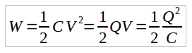
 A capacitor is an electric device capable of storing energy in the form of electric charges (electric field).