Back To Basics Episode 7: Everything You Need To Know About Inductors


In the last episode, we talked about the capacitor—the component that stores energy in an electric field and hates it when voltage changes. Today, we meet its magnetic twin.


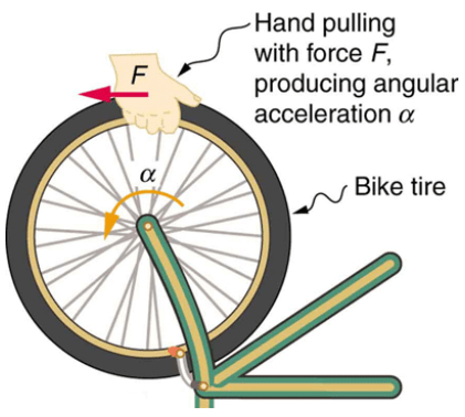
If I try to spin a wheel instantly, I cannot do it. Since the wheel has a mass, it has inertia and so it resists being moved. However, once it is finally spinning, if I try to stop it suddenly…. again, it fights me and prevents me from doing it.


In the world of electronics, we have a component that does exactly the same thing, but with the current. Like the capacitor tries to keep a constant voltage at its leads, the inductor tries to keep constant the current that flows through it with the help of a magnetic field.


It is the most stubborn component in a circuit. It is basically the mass of a circuit. If current is not moving through the wire, it doesn’t want it to start. If current is already moving through the wire, it doesn’t want it to change, or even stop.


Today, we are going to look at the physics of the inductors, why they can be dangerous, and how they are used in real world applications.


Anatomy of an inductor


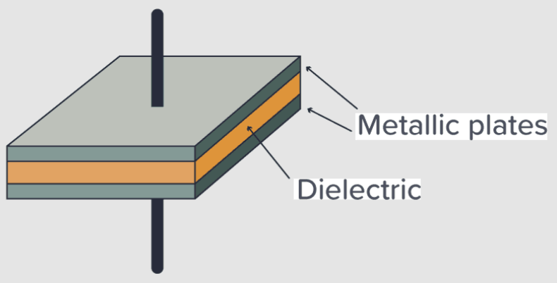
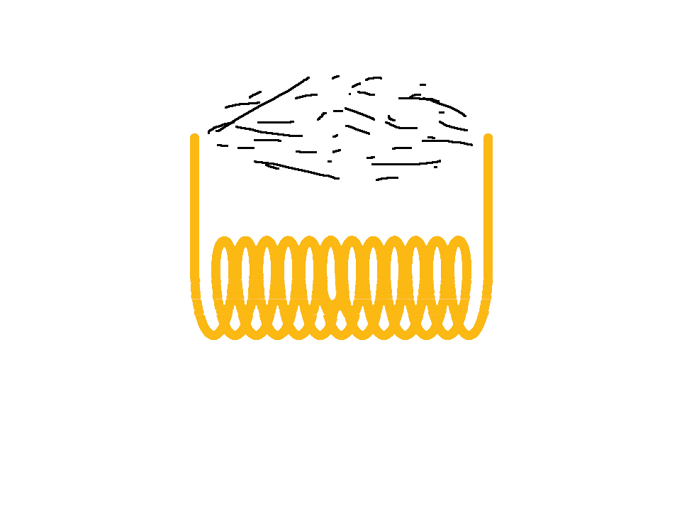
Physically, an inductor is the simplest component you’ll ever see. It is usually just a coil of wire. But don’t let the simplicity fool you.


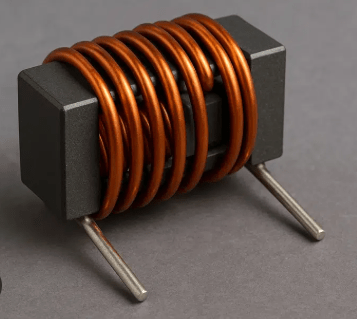
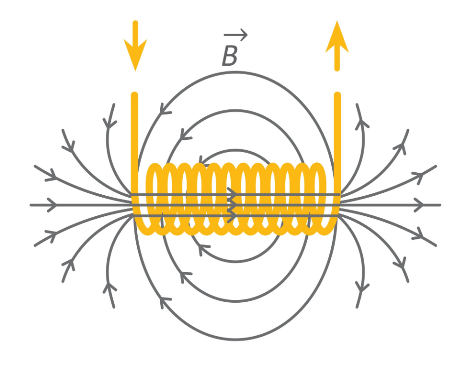
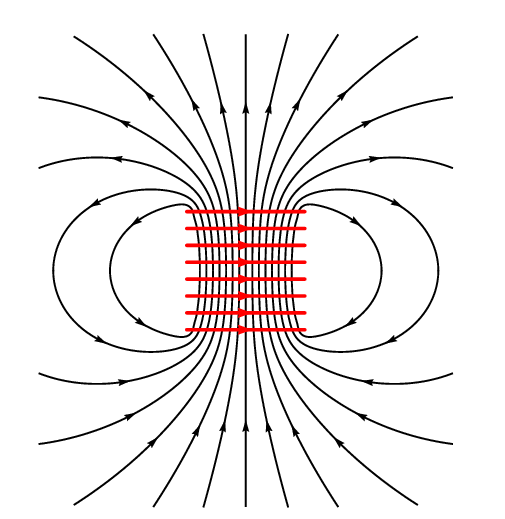
When current flows through a straight wire, it creates a small magnetic field around it. But when we wind that wire into a coil, a shape that we call solenoid, those individual fields stack up and reinforce each other.


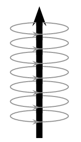
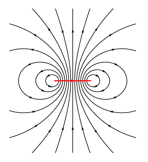
This creates a concentrated magnetic field through the center of the coil. And this is where the energy lives. While capacitors store energy in an electric field between plates, inductors store it in a magnetic field within the coil.
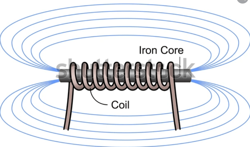
Additionally, what’s inside the coil matters just as much as the wire itself. We call the inside of the coil “core”.

If the core is made out of air, the strength of the field is low, and such inductors are normally used for high frequency circuits.


If the core is made of iron or similar ferromagnetic material, it will channel the magnetic flux and will intensify it, making the inductor capable of storing a much greater amount of energy.


If the core is made of ferrite, which is a ceramic like material containing usually silicon and iron, then the inductor acquires a much faster capability of switching from on to off and viceversa without the energy loss that we would get with solid iron.


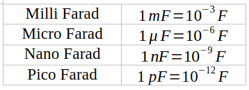
The ability of the coil to store energy in a magnetic field is called inductance, and it is measured in Henry, named after Joseph Henry, who discovered this property around the same time as Michael Faraday. The measure Henry is indicated with the capitol letter H.


How the inductor works


So, why the inductor resists to current changes? It comes down to a fundamental rule of physics called Lenz’s law.


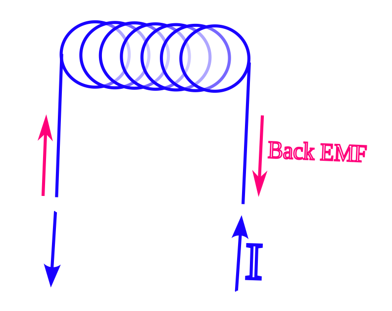
When we try to increase the current through an inductor, the magnetic field has to expand. But the expansion actually pushes back against the incoming current. We call this Back EMF, or Back Electromotive force. It’s basically like trying to push a heavy car: it takes a lot of effort just to get it rolling.


Let’s look at the math, but don’t let that scare you. It is just a way to describe the stubbornness of the inductor.

The voltage V across an inductor is defined by

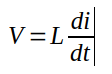
where L is the inductance and di/dt is simply the speed at which the current is changing.
Here is the magic: when we try to push current through, the magnetic field expands. According to Lenz’s law nature hates a change in magnetic flux. And so, the expanding field creates its own internal voltage, the back emf, that pushes back against the battery. It is literally an internal “ghost battery” fighting the actual battery.


Inductor behavior in DC vs. AC


Now, because inductors react to change, they behave totally differently depending on the type of electricity we feed them.


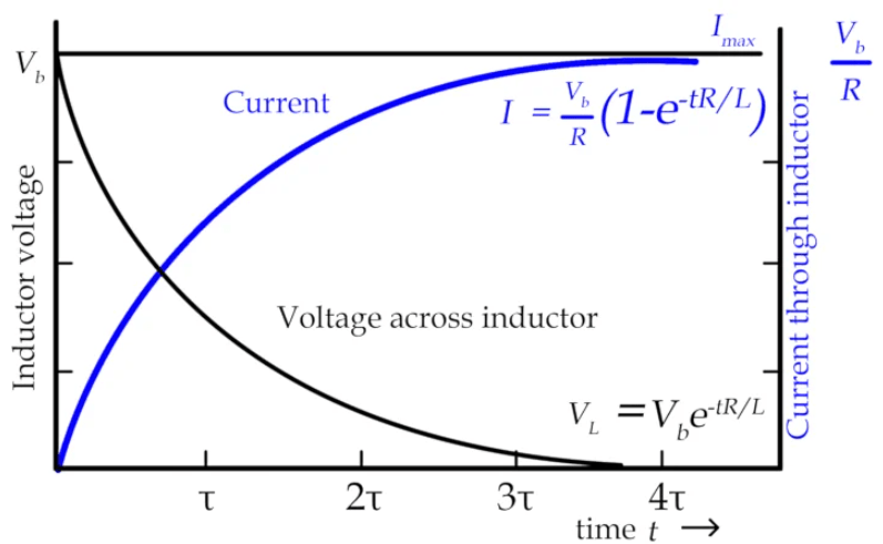
In a DC circuit, when we first flip the switch, the inductor fights the current. It acts like a wall, an open circuit. But, once the current is flowing steadily, the inductor gives up, it becomes just a regular piece of wire.


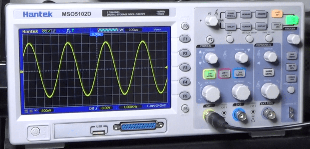
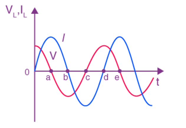
In an AC circuit, the current constantly changes direction. This means that the inductor is constantly fighting. We call this “fighting” Inductive Reactance. The higher the frequency of the AC, the harder the inductor fights it.


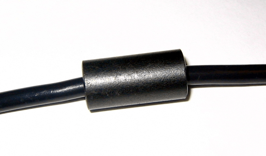
This makes them perfect for filtering out high frequency noise. They let the slow, steady power through, but block the high frequency noise. This is why you see those lumps on the laptop charging cables. They are actually inductors blocking the high frequency interference.


Real world applications

So, where do we actually use these things? Here are a few examples.


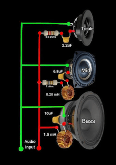
Filters: in the audio speakers inductors are used in crossovers to block high frequency sounds from reaching the woofer, ensuring it emits only those deep, clean, bass notes.


Chokes: used in power supplies to smooth out ripples in the current.


Transformers: if we put two inductors next to each other, the magnetic field of one can induce an EMF in the other. And that’s how they step power up or down for the electric distribution grid.


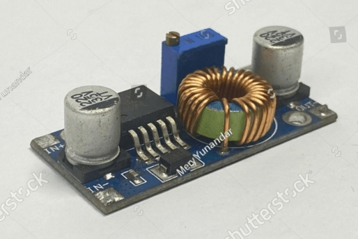
Buck converters: they are made with small transformers working at high frequencies.


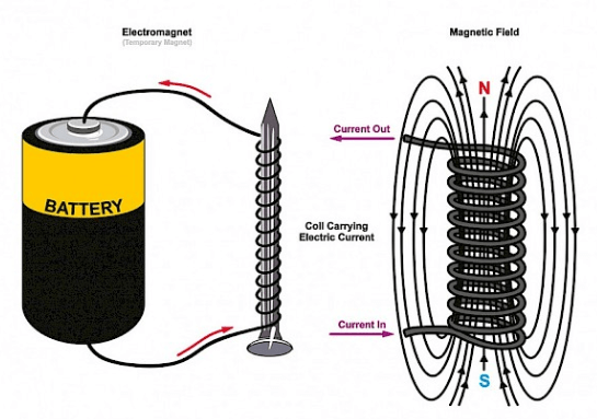
Electromagnets: simple coils, usually winded around a ferromagnetic core, that becomes real strong magnets when we make a current flow through their wires. They are used all over the places. And they are especially common inside electric motors, like the ones that power many kitchen appliances.


Sensors: have you ever seen those loop of wires buried under the asphalt at traffic lights? Those are inductors. When a car sits over them, it changes the inductance, telling the traffic lights circuitry that a car is there waiting for its turn to pass.


The inductive kickback


A word of warning now. Because an inductor wants to keep a constant amount of current, it can be dangerous at times.


If you have current flowing through a coil and you suddenly pull the plug, the magnetic field inside the coil collapses. But the energy in that magnetic field needs to go somewhere. What happens is that the inductor will convert that energy in a voltage spike with the polarity oriented in such a way that it will try to keep the current flow without a change.


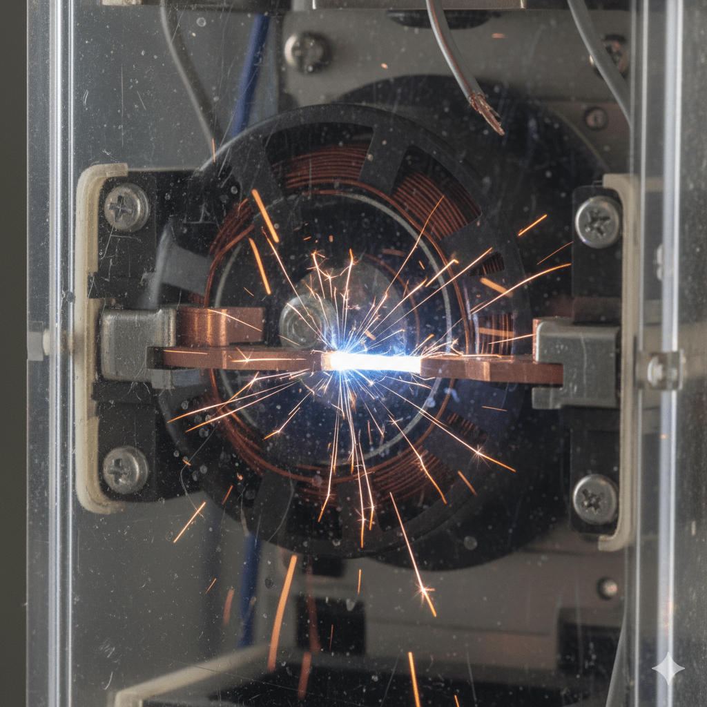
Have you ever seen a spark when you suddenly disconnect a wire from a circuit where current was flowing through it? That spark is caused by this inductive kickback produced by the inductance in the circuit. When you open the circuit, the inductor will generate a voltage high enough to make the current go through the air around the disconnected wires, thus the spark.


In electronic circuits, the inductive kickback may damage the semiconductors in the circuit. In such a case, we use a diode, in parallel with the inductor, oriented in such a way that it will behave like a short circuit toward the back EMF of the kickback, and it will behave like an open circuit during normal operations.

Here is an example: a transistor controlling the coil of a relay. The diode in parallel to the coil will short the kickback which, otherwise, would destroy the transistor.

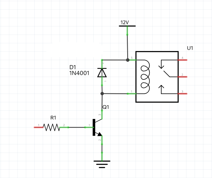
A diode connected like that is called flyback diode, because it will make the kickback fly away.


Inductor identification


Now that we know how inductors work, we need to know how to identify them on a circuit board. Unfortunately, this is trickier than it sounds, because inductors are masters of disguise.


Let’s start with the physical shape, and there are several of them.


The first kind of shape is the axial inductor: these look exactly like resistors. They are small, usually green of cyan, and have color bands.

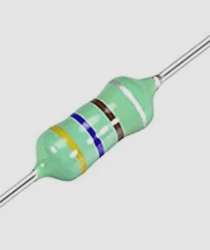
A pro-tip for you. If the body looks like a sea-foam green, then it is most always an inductor. If it is tan or blue, it is likely a resistor.


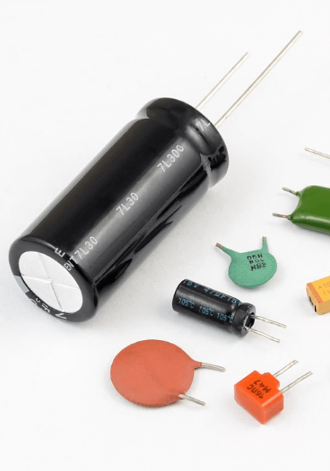
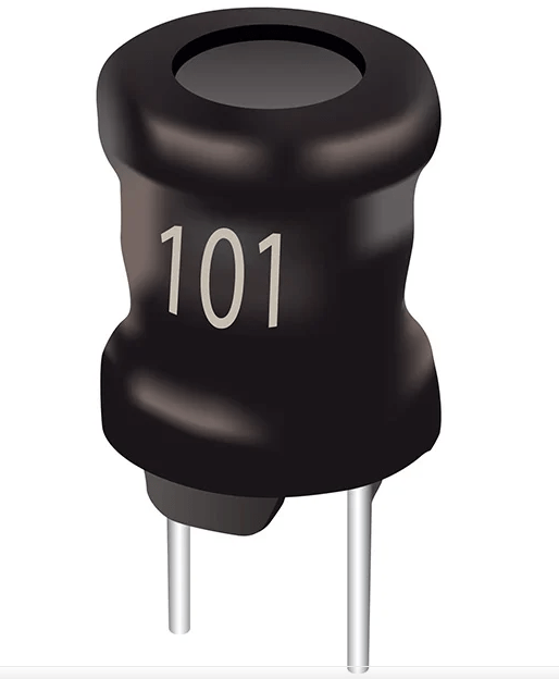
The second inductor shape is the drum or radial inductor. These look like little black mushrooms or weights. You’ll see the copper wire wrapped around a ferrite core, often covered in clear or black shrink wrap.


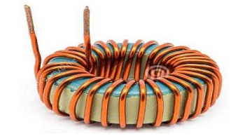
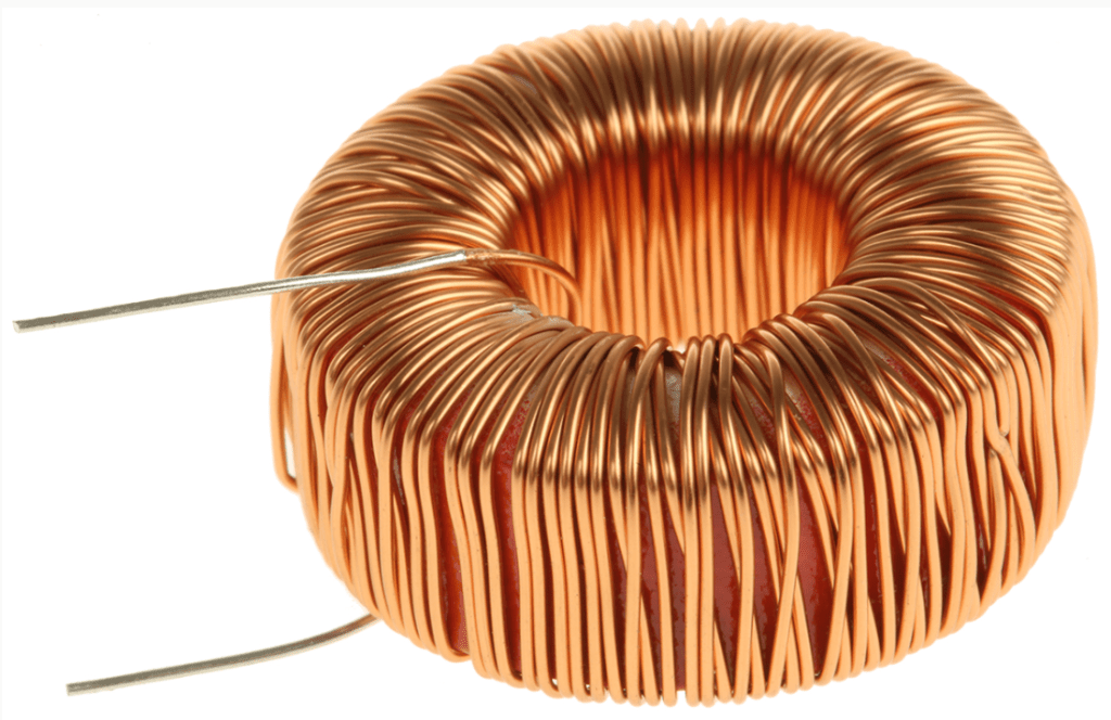
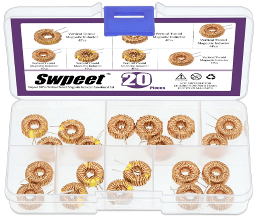
The next shape is the toroid. These are like small donuts. They look like a ring wrapped with wire. In this category we find usually high performance inductors used in power supplies.


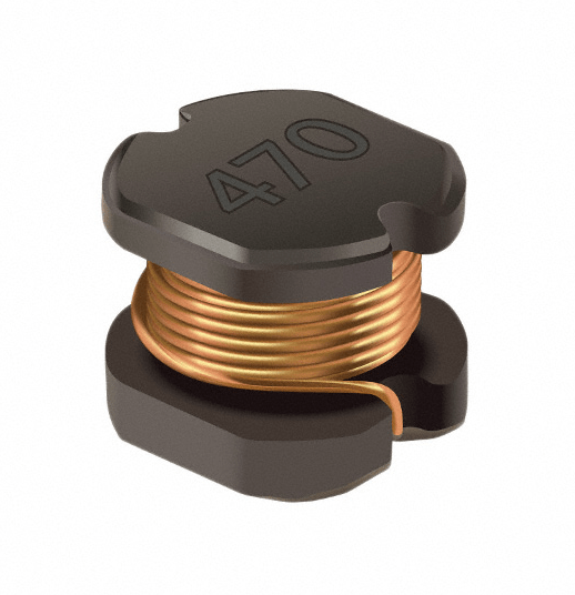
Last category I would like to talk about is the one of the SMD inductors. On modern boards, these look like tiny gray or black ceramic rectangles. Unlike resistors, they are usually taller, since they need space for winding the coil.


Now, how do we figure out their inductance value? Well, just like resistors, inductors use a code system. Their base unit for these codes is almost always the microhenry.

Let’s start with the color code, used for axial inductors. It’s the same colors used for resistors: black for 0, brown for 1, red for 2, and so forth.

Inductors can have 3, 4, or 5 bands, like resistors, and they are read exactly the same way as the resistors.


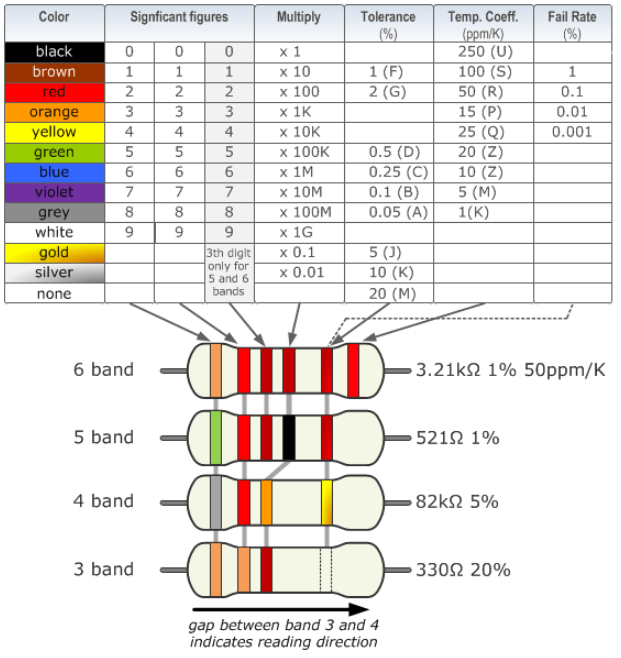
For example, the axial inductor from above has yellow, blue, black, and silver, which means 46 microhenry, and a tolerance of 10%.

Let’s now talk about the numerical code, present on the SMD and drum inductors. You might see a 3 digit number, like in the above drum indicor which shows on its case 101. The first two digits are the value, the third is the number of zeros after the first two digits.

This means that 101 translates to 10 + one zero, which means 100 microhenry.


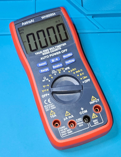
Like with resistors and capacitors, if in doubt, don’t guess, measure the value. The problem is that multimeters usually do not have a mean to measure inductors. You can still test the resistance which, for good inductors, should be almost zero, since it is just a coil of wire.
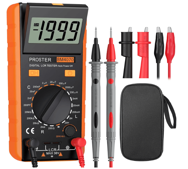
If you want to really measure the value, you’ll have to acquire an instrument called LCR meter, which is a high specialized instrument that take only measurements of inductors, the letter L, capacitors, the letter C, and resistors, the letter R.


The essential starter kit


Now, if you want to start using inductors in your experiments, you don’t need to buy every inductor on the market. Inductors are expensive and bulky compared to resistors, so you want to be strategic. Here is my “starter kit” recommendation for any hobbyist lab.


Begin with a must-have assortment. Don’t start buying individual values. Go to Amazon or eBay and look for an Axial Inductor Assortment Kit.

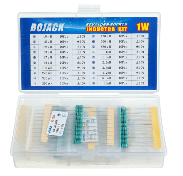
You’ll get usually 200 or 300 pieces in a small plastic box, with a bunch of different values.

They look like resistors, and fit perfectly into breadboards. The values usually range from 1 micro henry to 10 milli henry, and this covers about 90% of basic hobbyist filtering needs.


If you plan on building your own power regulators or buck converters, you will need toroidal inductors. Go with values like 10uH, 47uH, and 100uH to start with. Look for high current ratings, at least 2 or 3 amps. Power inductors are rated by how much heat they can handle before start having problems.


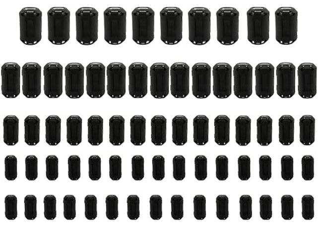
For noise management, you may also want to acquire a few ferrite bids. There aren’t technically coils, but they are essential. They are basically small cylinders of ferromagnetic material. You slide them over wires to choke out high frequency interference. If your project has a buzzing sound in the speakers or a flickering screen, a ferrite bead is often the cure.


Finally, if you are serious about inductors, a standard multimeter won’t cut it. Most cheap multimeters can’t measure inductance.
In such case, I recommend to pick up a cheap TC-1 Multi function tester, which you can find for about $20, and you can just plug an unknown inductor in, and it will tell you the value and the internal resistance instantly.


Better yet, buy a LCR meter, which will allow you to make precise inductance measurements, as well as capacitances and resistances. Some devices can even provide you with a full model for the component you are testing, giving you both its resistance, the series inductance, and the parallel capacitance, which is useful should you decide to work with high frequencies.


Conclusion

To summarize what we said so far:

inductors are everywhere. They are in your phone’s wireless charger, the crossover in your high end speakers, the massive transformers on your street corner, and so forth.

  • They store energy in a magnetic field.
  • They resist changes in current.
  • They are the high frequency blockers of the electronics world.

In our future videos of this series, we are going to continue our journey in the world of electronics, showing new types of components, and how to use them, as well as moving the first steps in designing you own circuits.
If you find this deep dive helpful, like it and subscribe.

I’ll see you in the next episode and, in the mean time…

Happy experiments!

Companion YouTube video:

Back To Basics Episode 6: The Absolute Beginners Guide To Capacitors


Welcome back to Back To Basics, our journey to master electronics one little bit at a time.


Think of your favorite gadget. Your phone, your laptop, even your car. Now, imagine if they just… stopped working. Not because the battery died, but because they couldn’t handle the noise of their own electricity.


Most people know about batteries but, today, we are talking about the unsung hero of the circuit board: the capacitor. It’s the component that can dump its entire energy load in a millisecond, smooth out a jagged power supply, and even keep your clock running when you pull the plug.


Today, in back to basics, we dive into the world of electrostatic storage. Let’s find out how these little cans and disks actually work.

What Is A Capacitor


Basically, a capacitor is a passive component that stores energy in an electric field. Unlike a battery, which uses a slow chemical reaction, a capacitor is all about speed.


To visualize this, imagine a plumbing system. If a battery is a huge water reservoir, a capacitor is a small pressure tank. It can’t supply water for hours, but if the main pump flickers for a second, the pressure tank kicks in instantly to keep the flow steady. It’s the ultimate shock absorber for electricity.


It is made of three main parts: two conductive plates, and an insulator in between, called a dielectric. When we apply voltage, positive charges pile up on one plate, and negative charges pile up on the other. The charges would like to reach each other, but the dielectric stops them. That tension is actually stored energy inside the capacitor in the form of an electric field generated by those charges.


We measure the ability to store charge in Farads. But, because a single Farad is actually a huge amount of energy, we most often use a small fraction of it: the millifarad, the microfarad, the nanofarad, and the picofarad.

Top Three Applications

Why do we actually use capacitors?

There are three big roles for them:

  • filtering and smoothing, where they turn bumpy DC voltages into a smooth and steady line.
  • energy storage, where they can provide a quick burst, for example for a camera flash or a subwoofer’s bass hit
  • signal coupling, where they allow AC signals, like music, to pass through a circuit, while blocking unwanted DC offset.


Now, not all capacitors are built the same. Here are three types that you’ll see the most often.


Ceramic capacitors: small, cheap, and non polarized, which means you can plug them either way. They look like little lentils and are perfect to deal with high speed filtering.


Electrolytic capacitors: these look like miniaturized soda cans. They hold a lot of energy but they are polarized, meaning they have a positive and a negative side. Hook them up backward, and things will get really messy. They are perfect for low speed filtering, for example in DC power supplies.


Film capacitors: Usually rectangular and green or red. These are very stable and great for audio circuits or high voltage power.

And, just to give you the full picture, here is a table I made where all the type of capacitors are listed.

In here, note that NP0 capacitors are a special kind of ceramic capacitors. Polystyrene and polypropylene are the typical dielectrics of film capacitors. Tantalum capacitors are a type of electrolytic capacitors, where the positive plate uses tantalum metal, and the dielectric is made oxidizing one side of the tantalum plate. As the other kind of electrolytic capacitors, these are also polarized.

Identify The Codes

OK, let’s say now we got a bunch of capacitors, all there sitting on the workbench. But how do we know which one is which? Unlike resistors, which use color bands, capacitors use numbers and letters printed on their body. The big problem is, different types of capacitors don’t speak the same language. And… yes, sometimes even same type capacitors don’t.

Let me tell you the most common ways to interpret the information on the capacitors cases.

And let’s start with electrolytic capacitors. They are the most straightforward, because they are physically larger, and the manufacturers have enough room to print the actual values directly on the side.

The capacitance is a number followed by the Greek letter mu and a capitol F, which stand for microfarads. For example, this one says 100uF. No math required.

Follows the maximum voltage rating, in this case 50V. Remember that you have to always use the capacitor at a voltage smaller than the rated voltage, or you’ll damage the capacitor.

Last, we have the polarity, this big stripe with the minus sign. That stripe indicates the negative lead of the capacitor. Note also that in an electrolytic capacitor, the negative lead is also shorter than the positive one.

Let’s now take a look at the ceramic capacitors. These capacitors are too small for full labels. Instead, they use a three digit code and their unit is always expressed in picofarads, or pF. The first two numbers are the value, and the third number indicates how many zeros you have to add to the previous two digits to provide their value in picofarad.

Additionally, when the number of picofarads is very small, in the order of only one or two digits, then the value can be directly expressed with those digits. In that case, we have only one or two digit numbers.

For example, on this one we read the digits 1-0-4. That means we have a 10 followed by 4 zeros. That gives us the number 100,000, so the value is 100,000 pF, or 100nF, or 0.1uF. And yes, we need a little math to interpret the values of these capacitors.

Here is another ceramic capacitor. This one has only two digits printed on it: 3-3. This means that the number 33 is the nominal value of the capacitor in pF.

Lastly, let’s take a look at a film capacitor.

These capacitors often use a mix. You might see a 3-digit code, like the ceramics, but you will also see a letter at the end. That letter represents the tolerance, or how accurate the nominal value actually is.

But wait, there is more: the rated voltage. This one can be expressed in three different ways. It can be written explicitly, or it could be missing, of there could be a code which is prefixed to the capacitor value.

If it is expressed in clear, then that is the actual rating.

If the voltage rating is not present at all, then it is 50V by default.

If it is encoded along with the capacitance value, then it can be one of those listed in the EIA standard. Here is the corresponding table for the most common.

As an example, the film capacitor above reads: 2A393J.

2A translates into a voltage rating of 100V; 393 translates into a value of 39,000pF, or 39nF, and the letter J at the end translates into a tolerance of 5%.

Here is the hole list of tolerances.


A pro tip for you now, valid for any kind of capacitor. If the text is rubbed off, or too small to read, or has any other problem that prevents you from reading it, don’t guess. Use a multimeter capable of reading capacitance. It will give you the live reading of exactly what that component is holding, and it’s the only way to be 100% sure before you solder the component in a circuit.

Pitfalls


Okay, now that we have covered some theory and some practical aspects, it’s time to take a look at what I call the ‘Wall of Shame’. If you stay in this hobby long enough, you will eventually blow up a capacitor. It’s almost a rite of passage! But to save you the jump-scare and the smell of burnt electrolyte, I want to show you the most common ways people accidentally kill or misuse their capacitors—and how you can avoid doing the same.
Here is my list #1 mistakes every beginner makes and how to fix or prevent them.

  • The polarity POP or: connecting an electrolytic capacitor backward. The consequence is that the internal dielectric breaks down, the electrolyte boils into gas, and pressure builds up until the safety vent bursts, or the whole capacitor pops. To prevent that, always look for the stripe on the side of the capacitor, which marks the negative lead, or look for the longer leg, which marks the positive lead.
  • Ignoring the voltage rating, or using a capacitor that is rated exactly for the voltage of the circuit or. worst, a capacitor with a smaller rating. In such a case, an excessive voltage can push the capacitor over its limits, causing it to leak or fail prematurely. Avoid that by always leave a safety margin. Use a capacitor rater 20 to 50% higher than the circuit voltage. If the circuit works at 12V, use a 16V or even a 25V capacitor.
  • The ghost charge. This has more to do with safety. Don’t assume a capacitor is off just because the device is unplugged. Capacitors, especially if large, can hold a dangerous charge for days or even weeks. Touching the leads can give you a nasty shock, or damage the multimeter if connecting the charged capacitor to it. Before handling the capacitor, discharge it. This can be safely done using a high value resistor ,like 1k, to bleed the energy off slowly.
  • Wrong type for the job, for example when using an electrolytic capacitor when a ceramic one should have been used instead. The result is usually an erratic behavior of the circuit. For example, using a large electrolytic capacitor near a micro-controller can cause the random reset of the micro-controller itself, because of the random electrical noise on the power line that the capacitor cannot get rid of. In such a case a small ceramic capacitor should be used for decoupling. Remember: electrolytic capacitors are good for bulk energy storage, ceramic capacitors are good for high speed noise filtering.
  • Soldering stress, or thermal shock. Holding the soldering iron on the capacitor leads for too long causes excessive heat that can dry out the electrolyte inside an electrolytic capacitor, of crack the ceramic layer of a ceramic capacitor, or melt the dielectric of a film capacitor. Always use a clean and tinned iron tip to be able to do make good soldered joints is a short time. You may want to see my video on soldering techniques for further information.

The Essential Capacitor Starter Kit

Before closing, here are some suggestions to create your own capacitors starter kit, an assortment of capacitors that covers 95% of the necessities for beginners projects, like Arduino, LED circuits, simple audio circuits, and so on. Start with a mix of ceramic and electrolytic capacitors. You can add more later.


Ceramic capacitors will be useful as non polarized noise killers. They are used for decoupling and filtering high frequency noise.
Useful values are:

  • 22pF, essential if you are building your own micro controllers, ad they are used in crystal oscillators.
  • 0.1 uF, the most common capacitor in existence. Every integrated circuit usually needs one of these right next to its power pin.
  • 1uF, good for general purpose filtering


Electrolytic capacitors will be useful as polarized power smoothers. These are bulk energy storage for power supplies. The most common values for beginner projects are:

  • 10uF, 25V or 50V. used for small scale power smoothing.
  • 100 uF, 25V. Great for stabilizing power rails in breadboard projects.
  • 1000uF, 25V. The big tanks. Used when dealing with motors or long LED strips of LEDs that pull a lot of current.

As an alternative, rather than buying individual values, search for capacitor assortment kits, on sites like Amazon, Adafruit, or Ali Express. They usually come in a plastic organizer box and are very cheap.

When buying a kit, look for capacitors rated at 25V or 50V. While 16V capacitors are smaller, a 50V capacitor can do everything a 16V one can, making it much more versatile for a beginner who might accidentally plug it into a 24V source.

Conclusion


So, there you have it: the humble capacitor. It is not just a tiny battery; it is the heartbeat and the filter of almost every circuit you’ll ever build.

I’ll see you in the next episode, and in the mean time…

Happy experiments!!!

Back To Basics Episode 3: The 6 Essential Tools For Your First Electronic Lab

Hi there, welcome back to the “Back to Basics” series.

So you’ve decided to dive into electronics. You’re watching tutorials, you’re looking at schematics, but then you hit the wall: what tools do I actually need, and where do I start without spending a fortune? That’s the biggest barrier for everyone.

Today, we’re building your first electronics workbench. We’re going to break down the six most essential pieces of gear—from the absolute must-haves to the powerful diagnostic equipment you’ll eventually crave.

I’m structuring this into three simple tiers, to make it progressive.

Tier 1: The Must-Haves, which are the stuff you need on Day 1 to even build a circuit.

Tier 2: The Essential Builder Stuff or how to make your project permanent.

Tier 3: The Diagnostic Duo or how to troubleshoot and see signals you can’t see with your eyes. That’s for when you need to actually see the electricity doing its thing.

Let’s start building!


Tier 1 – The Absolute Must Have: The Prototyping Pair

Let’s dive into tier one. The prototyping pair. First up, the breadboard, your best friend for starting out. It’s basically a temporary solder-less lab.

It will let you try things out, make mistakes, swap components. Basically: super fast iteration.

The key thing to get, though, is how it’s wired internally. Those middle columns, they connect vertically. Little strips of metal inside. You plug your component legs into different rows in the same column, and they’re connected.

Those long strips on the sides, the power rails, run horizontally all the way from left to right. Knowing that difference saves hours of confusion. So vertical columns for components in the middle, horizontal rows for power on the sides. Simple when you know it.

Once you’ve built something, you need to check if it actually works or why it doesn’t. Which brings us to the second must-have in Tier 1, the digital multimeter, or DMM. The Swiss Army Knife. You just can’t debug what you can’t measure. It’s fundamental. Safety, too. Measures voltage, current, resistance, the basics.


Tier 2 – The Essential Builder: Permanent Connections

Let’s now move on to Tier 2, the essential builder.

So your breadboard circuit works perfectly. Awesome. But now you want to make it permanent. Put it on a proper PCB or maybe a perf board. And that means soldering. You need a soldering iron and you need solder. This is where things get hands on. But what iron to use? There’s so many types.

The key thing is temperature control. You need to be able to set the right temperature for your soldering components. Too cold, and you obtain bad joints. Too hot, and you damage the components.

And then you need the proper technique. This is where people often mess up, big time. The absolute number one rule is: melt the solder with the components to attach together, not with the solder tip. You touch the hot iron tip to both the component leg and the copper pad on the board at the same time. You hold it there for a couple of seconds, just long enough for them both to get hot. Then you touch the solder wire to the joint, not to the iron tip. And the heat from the pad and the leg melts the solder, making it flow nicely around them. You’re aiming for that classic shiny volcano shape, a little cone. Not a dull blob. Definitely not a dull blob. Dull or lumpy means a cold joint, which will probably fail later.

Also, always use a fan or work in a well-ventilated area. Those fumes aren’t good for you.


Tier 3 – The Diagnostic Duo: Seeing The Unseen

Now tier three, the diagnostic duo. This sounds more serious. Well, it is, in a way. This is for when you move beyond simple DC circuits into things that change over time, like audio signals or digital clocks.

First in the list is the function generator, or the signal injector. Its job is basically to create predictable electrical signals.

Known, clean waveforms, usually sine waves for analog stuff, square waves for digital, maybe triangle waves for ramps. Why is that necessary? Can’t you just use the signal from, say, the phone’s headphone jack? You could, but is that signal perfectly clean? Does it have noise? Is its amplitude exactly what you think? A function generator gives you a reliable, known-good input. So you’re eliminating unknown variables.

If you test a filter circuit with a perfect sine wave from the generator and the output looks wrong… Then you know the problem is in your circuit, not just some garbage coming in. It’s about controlled testing.

And now the function generator partner, the oscilloscope. The big gun. This is arguably the most powerful debugging tool in electronics. It lets you see electricity.

It draws a graph. Voltage on the vertical axis, time on the horizontal. So you can see exactly how a signal changes, millisecond by millisecond or even faster. So you can see noise, distortion, timing glitches. Things way too fast for a DMM.

And the key to using it effectively, the thing that unlocks its power, is the trigger control. It just tells the scope when to start drawing the waveform on the screen.

It looks for a specific voltage level on the signal. So every time the signal hits, say, one volt while rising, the scope starts drawing from that exact point. And because it starts drawing at the same point on the waveform over and over, that fast-moving signal looks like it’s standing perfectly still on the screen. Makes analysis possible.

So you hook the function generator output, like a 1 kHz sine wave, to your circuit input and then probe the output with the oscilloscope. And you can see precisely how your circuit affects that signal, stable and clear, thanks to the trigger. That’s how professionals diagnose high-speed problems.

Conclusion

Let’s recap quickly, by function.

Tier 1, the must-haves for prototyping are the breadboard and the DMM.

Tier 2, the essential builder for making it permanent, is the soldering iron and the solder. And don’t forget the ventilation!

Tier 3, the diagnostic duo for seeing the unseen signals, are the function generator and the oscilloscope.

That’s the core toolkit for your lab.

The really crucial takeaway is that you don’t need everything on day one. It’s scalable.

Start with Tier 1. Get comfortable prototyping. Then, when your projects demand permanence, you move to Tier 2.

And only when you’re dealing with signals where timing and shape really matter, like building an audio filter or maybe something with a micro-controller, you invest in Tier 3 for that deeper diagnostic view.

Start small, build your skills, and let your projects guide how you grow your lab. Build it organically.

You don’t need everything at once!

Finally, here is the link to the companion YouTube Video, which you may want to watch for additional details.