Inductors Basics

Describing basic functionality of the inductors and how they are treated when connected in series or in parallel.

What is an inductor? How does it work? And how we handle inductors when they are connected in series or in parallel? Here are the answers.

An inductor is an electric device capable of storing energy in the form of a magnetic or electromagnetic field.

inductor

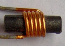
In its basic form, an inductor can be made of a single loop of wire, or several loops (solenoid). These loops can be arranged in air or on a ferromagnetic core.

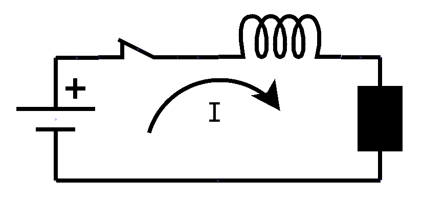
When an inductor is connected to a battery, a current starts flowing in the circuit. The current that flows inside the inductor generates a magnetic field, like the one that would be generated by an actual magnet. This field stores an amount of energy, the same way an electric field does.

inductor_circuit

If the battery is suddenly disconnected, the energy that was accumulated in the inductor must be somehow released. but the energy cannot be released instantaneously, it needs to be released a little bit at a time. And since the energy depends on the current flowing in the inductor, the inductor tries to keep the it running, even if the battery is no more connected. To do so, it uses the energy stored into the magnetic field to generate a voltage at its terminals to keep the current going.

inductor_open_circuit

However, since the inductor is now connected nowhere, current cannot flow, unless the voltage is so high that the current can flow in the thin air. And that is exactly what happens: the voltage increases so much that there is a sudden discharge of current through the air, in the form of a spark, that dissipates all the energy that was stored in the inductor. This spark is the one you may sometimes notice when opening a switch that is powering a lamp or a motor, or when you pull the plug from a device that was working using a considerable amount of current.

Similarly to the case where the current is suddenly removed, an inductor generates a voltage also when the current is just changed in intensity. In this case, the voltage is created to react to the change in current, trying to keep it to the same value, so the energy can be conserved.

In both cases, the amount of voltage is proportional to the change in current (ΔI) and inversely proportional to the amount of time in which the current changes (Δt). In other words, the faster the current change, the higher is the voltage.

For a specific inductor, the ratio between the change of current and the interval in which that happens equals the voltage generated by the inductor divided by a constant that depends on the physics dimensions of the inductor. Such constant is called inductance, represented with the letter L, and can be calculated with the following experimental formula:
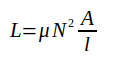
inductance_formula

where:

μ = permeability of the material inside the coil

N = number of turns making the coil

A = area of the cross section of the coil

l = length of the coil

L is measured in Henry.

μ is the product of the permeability of the void (or air) and the relative permeability of the material:mu

The voltage at the terminals of the inductor is therefore calculated as:

vdit

We can now calculate the energy stored in the magnetic field of an inductor as the integral of the power, which is obtained multiplying the voltage at the inductor and the current that flows through it:

inductor_energy

which, considering the value of the voltage previously calculated, can be solved as follows:

inductor_energy_value

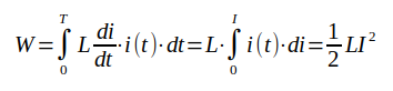
where I is the current flowing through the inductor at the time the energy is calculated.

When choosing an inductor for a circuit, the following parameters must be considered:

  • the value of the inductance in Henry

  • the max current the inductor can sustain; failure to specify that could cause the inductor to overheat, since the wire could be too thin to deal with the required current;

  • the max voltage that can be applied to the inductor; an excessive voltage on the inductor could cause sparks due to insufficient insulation of the wire.

Inductors In Series

Let’s consider a series of inductors of different inductance values and let’s calculate the equivalent inductance.

inductors_in_series

All the inductors, being in series, are traversed by the same current. And since each inductor has its own inductance value, each one will store a different amount of energy:

inductors_series_energies.png

The total energy stored in the inductors is therefore:

inductors_series_total_energy.png

So, the equivalent inductance is clearly:

series_inductance.png

which we can generalize as:

series_inductance_gen.png

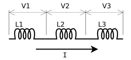
Inductors In Parallel

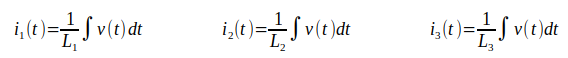
In the case of inductors in parallel, they are all subject to the same voltage and are traversed by a different current:

inductors_in_parallel.png

parallel_inductors_voltages.png

From these equations we can find the currents by integration:

parallel_inductors_currents.png

The total amount of current is therefore:

parallel_inductors_total_current.png

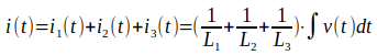
So we can say that the equivalent inductance of a parallel of inductors can be determined through the formula:

parallel_inductors_formula_1.png

or, more in general:

parallel_inductors_formula_2.png

All the formulas presented here are very general and can be applied to both DC and AC circuits. Note, however, that since AC circuits have a variable voltage and current, the application of the formulas in AC is a little more challenging then in DC. But this is a story for another time.

A Tester For Zener Diodes

Zener diodes are used for several purposes, from providing a reference voltage, to protecting sensitive circuits from being destroyed by the wrong input.

Today, I will show you how these diodes work and how to build a simple circuit to measure their most important characteristic, the reverse breakdown voltage. To know more on this topic, please watch the companion video posted on YouTube.

A zener diode looks like a regular diode and actually behaves as such when directly biased (positive voltage on the anode).

However, when inversely biased (negative voltage on the anode), a zener diode behaves in a completely different way.

Let’s take a look at its characteristic I-V diagram:

zener_characteristic

You can see that in the region of direct (or forward) bias, the zener behaves just like any diode. It also seems like in the inverse bias it behaves like a regular diode.  However, there is a big difference between the two.

For a regular diode, the reverse breakdown voltage is very high, in the order of 100V or more, sometimes much more. Such high that you never think at it when you use regular diodes, and you assume that with inverse bias the diode just does not conduct electric current.

For a zener diode, instead, the reverse breakdown voltage is low, in the order of one or two digit volts. Therefore, it is very easy in an electronic circuit to bring this kind of diode to reach the condition when it will start conducing electric current even if inversely polarized.

We actually exploit this behaviour to create reference voltages, or to provide a protection against unwanted voltages at the input of certain circuits, or a ton of other things.

The behaviour of a diode depends in fact upon the way it was fabricated, and in particular upon how it was doped. Regular diodes are lightly doped, while zener diodes are heavily doped. Depending on the amount of doping on both the P and the N side of the junction, the reverse breakdown voltage changes. That way, manufacturers can create zener diodes within a large range of breakdown voltages.

Problem is, manufacturers often don’t put the value of the breakdown voltage on the body of the components. Instead, they put some internal code or, sometimes, nothing at all.

So, if you had a number of such diodes on your workbench, how to distinguish them from one another?

Meet the zener tester.

It is a device that allows you to measure the reverse breakdown voltage, so you know if the diode works and what that voltage is.

How such a tester works? From the I-V diagram above, you can see that the characteristic of the zener diode is an almost vertical line when polarized in the reverse bias region. For any current value in that vertical line, the voltage is always the same and corresponds to the breakdown voltage. So, if we circulate a current at any point of that vertical line, we can measure at the terminals of that diode its breakdown voltage.

The zener tester I’m showing you today does just that: forces a current into the zener diode so we can measure the value of the breakdown voltage. We choose this current in such a way that it is high enough to stay away from the point where the characteristic is not linear, but low enough to avoid dissipating inside the diode a power that the diode itself cannot handle.

The following link allows you to download an archive containing the schematic of such device, along with the OpenSCAD code to 3D print the box for the device.

zener_diodes_tester_files

In the schematic you’ll see that I used a ready-made boost converter and a digital voltmeter. Here are the links to the store where I bought them. Of course you are free to use any other equivalent component. It will work as well.

BOOST CONVERTER

DIGITAL VOLTMETER

Please make sure to watch the YouTube video that completes the information I provided in this post. Between the two, you should have a complete view of the design of the device and should be able to build it.

Happy experiments!


Theremin v.2 Power Supply Design

theremin-v2-power-supply

For the new version of the Theremin, I have chosen to use a dual 12V power supply. This will have more flexibility because it will allow me to use more sophisticated units, possibly using op-amps.

The circuit is very basic: it uses a dual 14V transformer (not shown in the schematic) capable of providing 1.5A at its output.

A dual transformer is made up as in the following picture.

center-tapped-transformer

Is has a primary winding that is connected to the AC power supply outlet, and a secondary winding with a center tapped wire that is usually put to ground on the low voltage circuit side.

Voltage between either end wire of the secondary and the center tapped wire is usually the same (with the exception of specifically made transformers), which we call V.

The voltage measured between the two end wires of the winding is instead two times V or 2V.

Sometimes, instead of having a single secondary winding, we have two, carrying the exact same voltage. In this case, we can connect together the two closest wires and consider that as the center tapped wire. Then everything works as the first kind of transformer.

transformer-trans64

The AC current of the transformer is converted in to a DC current through the usage of a bridge rectifier and the capacitors C1 and C2.

The bridge rectifier converts the sine wave coming from the transformer into a fully rectified wave.

Full-wave_rectified_sine

Then, the capacitor that follows (in this case C1 and C2) starts charging over the ascending sides of the wave and discharging, partially, over the descending sides of the wave, basically filling the wave in between crests and making it look like more a straight horizontal line with some disturbance in it that we call ripple (the red line in the following picture).

ripple

In general, depending on the use of the power supply, we define a maximum value of the ripple that the circuit can handle.

In our case, we need to make sure that the voltage at the input of the regulators never goes below 14.5V, according to the data sheet, otherwise the regulator will not function properly.

The peak voltage provided by the transformer is its RMS value multiplied by the square root of 2, or:

peak_voltage

The minimum voltage we can have at the input of the regulator is:

regfulator_input_voltage

This is the max value of ripple that we can sustain.

To calculate the capacitor necessary to obtain this ripple, we use the following formula:

capacitance calculation

where f is the frequency of the alternate current which, in the USA, is 60Hz, and Ix is the maximum current that the power supply needs to provide.

So, we would need a capacitance value, for C1 and C2, of 2358uF.

However, the Theremin circuit will really not draw 1.5A from the power supply, so we can stay a little conservative, and use the closest value below the calculated one, which is 2200uF.

At this point we can safely say that the voltage on the output of the regulators will be exactly 12V (positive or negative, depending on the output side).

To further help the regulator, and preventing the current through it to go too close to the 1.5A threshold, where the regulator would not work anymore because the ripple becomes too high, we add to the output of each regulator another electrolytic capacitor, this one with a value at least equal to the capacitance value that we did not put at the input side. Since at the input side we put a capacitance of 2200uF instead of 2358uF, we will need a capacitor of at least 158uF.

However, to stay totally safe, I decided to use a capacitor at least 5 times higher, so I used the value of 1000uF for C3 and C4.

And finally, I added an extra capacitor (C5 and C6) to shunt toward ground any RF frequency that would travel back from the Theremin oscillators toward the power supply. A 0.1uF value is what is suggested by the data sheet of the regulator, so I used just that.

Why did I use this capacitor if there was already a 1000uF in there?

The reason hides in the way the electrolytic capacitors behave. In short, the electrolytic capacitors do not work well at high frequencies, so we need to add the extra 0.1uF capacitor, which is not an electrolytic one, to work in that range of frequencies. And since the range of frequencies is much higher than the one of the 110Vac outlet, a very small capacitance is enough to do the job.