Everybody knows that an electric wire, usually made of copper, is a conductor. And everybody knows that all metals are conductors.

Everybody also knows that plastic is a good electrical insulator, as well as other materials such as glass and rubber.

But how about semiconductors? What are they? And how do we really distinguish among conductors, semiconductors and insulators?
To answer all these question we need to look deeper inside the materials.We know that matter is made of atoms, and atoms are made of protons, neutrons and electrons. Protons and neutrons reside at the center of the atom structure, called the nucleus. Electrons are allocated all around the nucleus, at a long distance from it, relatively to the scale of the nucleus itself.
Electrons have a certain amount of energy, that is always an integral value of a certain amount that is called quantum of energy. Depending on the amount of energy they posses, they are locate closer or farther away from the nucleus. The more energy, the farther they are.
Based on quantum mechanics, which we are not going to talk in details in this context, electrons occupy bands of energy. The farther bands in the atom are the so called Valence Band and Conduction Band.
The valence band contains all those electrons that allow the atoms to stick together and forming molecules by bonding with other atoms of the same or a different substance.

For certain materials, rather than having molecules, the atoms form what is called a crystalline lattice, which is the case we are more interested in this context. It is worth noting that a new theory, highly based on quantum mechanics, is also distinguishing between actual crystalline lattices and material networks. However, for all the scope and purpose of this context, we will make a simplification and name both of them as crystalline lattices.
 (This picture, courtesy of Wikipedia)
In certain conditions, electrons in the valence band can jump to a higher level of energy, thus moving in what is called the conduction band. In the conduction band, electrons are no more stuck to their own atoms, but can start moving freely in the lattice that makes up the material. When that happens, we can control their movement by applying an electric field by the means, for example, of a battery. The voltage of the battery, applied to the two ends of the same block of material (for example a wire), produces the electric field inside the material and forces the electrons to move toward the positive electrode of the battery while, in the mean time, the negative electrode of the battery provides electrons to the material, to replace those that have entered the positive electrode of the battery.
Don’t think that electrons move very fast when they do that. Electrons, in fact, move very slowly, but it is the huge amount of them that help creating a measurable current.
Then you would ask: but when I turn the switch on, the light comes out of a lamp instantly. If the electrons move slowly, shouldn’t a lamp emit light only after a while?

Well, yes and no. In fact, the lamp does not light up immediately. It takes a certain amount of time to do that. But that time is so small that for us the event happens instantly.
Also, when you turn the switch on, the electrons closest to the positive electrode move into it almost immediately, not because they are fast, but because they are so close to it. At the same time, new electrons are fed to the material from the negative electrode. So, at the end, all the electrons in the wire start moving simultaneously inside of it, causing the current to start flowing immediately.
But I am digressing. Let’s go back to our primary subject.
We have talked about electrons in the valence band and the possibility they have to jump to the conduction band and, thus, helping creating a current if we apply a voltage.
But how much energy do the electrons need to jump to the conduction band?
Here it comes the definition of conductors, semiconductors and insulators.

In the materials called conductors, the level of energy that the valence electrons need to jump to the conduction band is basically ‘0’. In fact, valence band and conduction band overlap each other and, therefore, some or all the electrons in the valence band are also, already, in the conduction band. This happens mostly with metals, like copper, iron, aluminum, and so forth. Depending on the particular metal, the conduction and valence bands are more or less overlapped. Those material where there is more overlap are those that conduct electricity better. Those material where there is less overlap, are those that are worst to conduct current, although still conductors.
In the materials called insulators, the gap between the valence band and the conduction band is so high that electrons cannot jump from the valence band to the conduction band, and so they cannot generate an electrical current.
Of course, if we apply a voltage high enough, we can still provide them the energy to make the jump. However, in that case, because of the very high voltage, electrons jump from one band to the other in a disruptive way, causing the material to break. Once that happened, the insulator loose its property and it is no good anymore as such.
Finally, in the materials called semiconductors, the valence band and the conduction band are separated, but close together. It is relatively easy for an electron in the valence band to jump to the conduction band if we only heat a little bit the semiconductor, maybe just with our bare hands. The heat provides enough energy to the electrons to jump to the conduction band. However, not many electrons will do so, unless we keep heating the semiconductor. So, at the end, although capable of conducting some current, semiconductors are not good in doing so. Thus the name of their category.
In this article, we have talked about energy bands in materials, and how materials behave based on the position of the two highest energy band levels.
We have said that conductors are those were valence and conduction bands are partially overlapping.
Conversely, insulators are those that have a high gap in between the valence and the conduction bands.
And finally, semiconductors are those somewhat in between. For them, the valence and conduction bands are separated with a gap, but that gap is small enough to allow, under certain conditions, for the electrons to jump from the valence to the conduction band. That’s why they perform poorly both as conductors and insulators. However, we will see later on how semiconductors can be of great advantage for us, as long as they are treated in a certain way. They are those that allow us to build all the wonders of modern electronics.

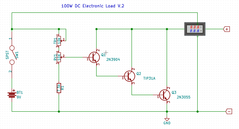
 A classic method for doing so is to use a rheostat, which is essentially a potentiometer capable of dissipating the amount of power produced by the power supply. The resistance of the rheostat can be changed and therefore different amount of currents can be used to test the power supply. However, rheostats are big, heavy and cumbersome.